 Engine controls link the firewall-forward installation to the pilot. They are simple, but they need to be carefully considered and well made to make your flying experience safe and enjoyable. Typically, the controls consist of the throttle, propeller control, mixture control, carburetor-heat control and cabin-heat control. Aircraft with fixed props obviously don’t need prop controls. Those with fuel injection don’t need carburetor-heat controls, because the icing problems that threaten carburetors do not have the same effect on fuel-injection systems. Some certified airplanes have alternate intake-air sources, even with fuel injection, but these are not commonly seen on Experimental/Amateur-Built airplanes.
ACS makes a popular line of control cables that is widely used on E/AB airplanes. They have appropriate knobs attached to solid wires that travel through wound-wire sheaths that are available bare or covered with a polyolefin plastic. The engine ends of these controls come with bare wires and threaded ends with 10-32 threads or with ¼-28 threads. The threaded ends can then be fitted with rod ends and bolted securely to the carburetor, fuel-injection system or propeller governor as needed. Solid-wire ends are more commonly used for carburetor-heat and cabin-heat controls.
Some care should be taken when ordering control cables with threaded ends. Only a small amount of adjustment is available in the length, and they really can’t be cut. It is easiest to first use a stock-length control cable and trial-fit it in your airplane. From there, you can measure how much longer or shorter your actual cable will need to be. Then you can order the exact length you need. Some kit manufacturers will sell you cables pre-made to the correct length for your particular airplane and engine combination, but in other cases you will have to figure it out yourself. This isn’t hard to do, but it can be difficult to get it right if you skip the trial-fitting step. Just remember, if you custom order a cable that is the wrong length, you will not be able to return it.
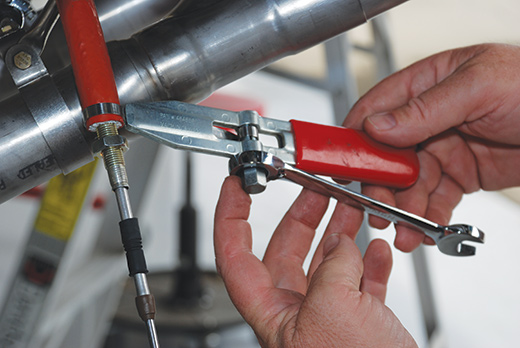
A throttle cable being protected with Aeroquip Firesleeve. This low-cost tool from Aircraft Spruce makes it easy for the amateur builder to turn out professional-quality work.
Throttle Control
Throttle controls come in two types, vernier or friction lock. Each type has its adherents, but all new certified airplanes come with friction-lock throttles. The case for friction-lock controls is that in case of an emergency such as a go-around, the friction-lock throttle (assuming the friction lock is loosened) is much more responsive, and therefore safer. Vernier fans like the fine adjustment possible with that type of throttle and argue that the unlock button on the vernier throttle control makes it just as safe as the friction-lock control. Most people learned to fly with friction-lock controls and are more comfortable with them. This is also the current FAA standard for certified airplanes. On the other hand, many older airplanes have, or at least once had, vernier throttle controls. Both types are available, so you can make your own choice.
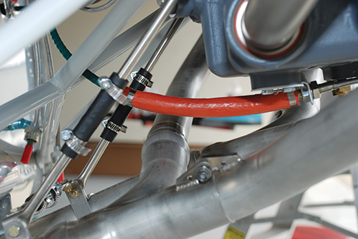
The throttle-cable routing required for this RV-8 installation puts the cable pretty close to hot exhaust pipes. Aeroquip Firesleeve will protect the cable from this potentially damaging heat. Without this protection, a clearance of at least 1.5 inches is recommended.
Typically the throttle control is black and has a smooth knob (current FAA standards), but white knobs are also available. It should be located toward the left whenever the controls are clustered together. Piper-type levers also work well for engine controls and are found on popular planes such as the RV-8 and others with tandem seating, but they are less common in planes with side-by-side seating. Either way works, but deviating from one of those standard configurations should be avoided for the sake of safety.
Best practice calls for a throttle control that has a range of motion that slightly exceeds the full travel of the carburetor or fuel-injection servo. In other words, the range of motion of the throttle should be limited by the stops on the carburetor, not the limits of travel of the throttle control. This extra travel is called “control bounce” or “cushion.” This is in keeping with standard aviation practice, wherein the thing being controlled limits the travel of the control, rather than the thing doing the moving setting the limits. When checking control travel, work the actual controls from the cockpit, not at the engine-compartment end. This is the best way to ensure that everything will work properly in flight.
Propeller Control
If there is a constant-speed propeller on your airplane, you will need a propeller control. In some cases, it will be an electrical switch, but in the vast majority of cases, it will be a mechanical propeller control that is similar to the throttle control. Prop controls differ from throttles in that they are almost always vernier controls, which allow for the fine adjustment of the prop governor. The standard configuration for the propeller control is a blue, fluted knob. In the case of a lever control, a blue knob with flutes in it would be typical and is the current FAA standard for certified airplanes. The shape and color of the propeller control in any case should feel and look distinctly different from the throttle. In all cases, it should be located immediately to the right of the throttle. There should never be any doubt about which control is which in an emergency situation, even for a pilot who is unfamiliar with the airplane. Safety requires controls that clearly do what any pilot would expect them to do.
The travel of the propeller control should meet the same basic standards outlined in the throttle-control section. Any vernier control should always have a release knob in the center of the control, but the quick response needed for a throttle is less of a concern for the propeller control, which should already be fully forward in a takeoff or landing situation. Be sure to allow enough space between controls for safe, independent operation. A spacing of about 2.5 inches on-center seems to work well.
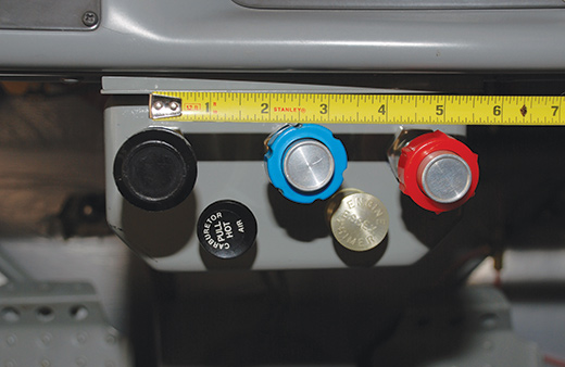
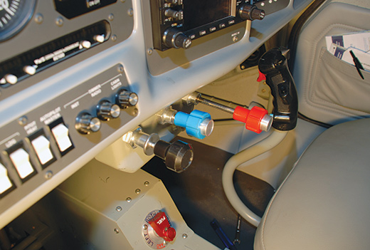
This is a typical installation of push/pull-type engine controls. Note the spacing of 2.5 inches on-center for the controls. This keeps the installation compact while still allowing enough room between controls. Note the label on the carburetor-heat control and its location near the throttle.
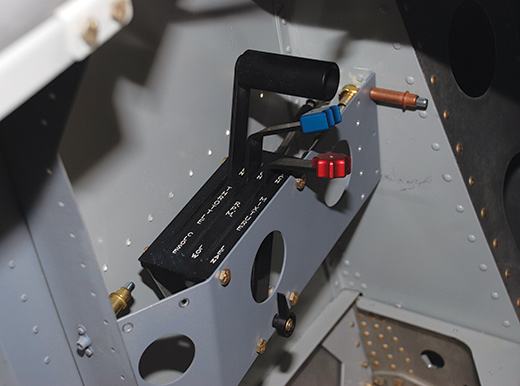
This control quadrant is being installed in an RV-8. It is well labeled and consistent with current FAA recommendations for the shape and color of each engine control. One would expect nothing less from Van’s.
Mixture Control
The mixture control uses a red knob with ridges to distinguish it from other controls. It is always located to the right of the throttle control unless there is also a propeller control, in which case it is located to the right of the propeller control. The same requirements for safe clearance and proper travel apply to the mixture control, which is usually a vernier control, again to allow for fine adjustment of the mixture. A simpler push/pull control with a built-in ratcheting mechanism can also be used for the mixture control. This type of control was once found on many certified airplanes before the FAA adopted its current standard. Whichever type of knob you use, it should still be red, and, as a precaution, it would be a good idea to label it “Mixture” to distinguish it from similar knobs for cabin heat and carburetor heat.
Carburetor Heat and Cabin Heat
The carburetor-heat control should be located near the throttle so that it can easily be shut off as the throttle is being applied in case of a go-around. It is preferable that both controls can be pushed forward at the same time with the motion of one hand. The carburetor-heat control is normally a simple push/pull control, although a ratcheting control could also be used. It should be clearly labeled to distinguish it from other similar-looking controls like the mixture or the cabin-heat control.
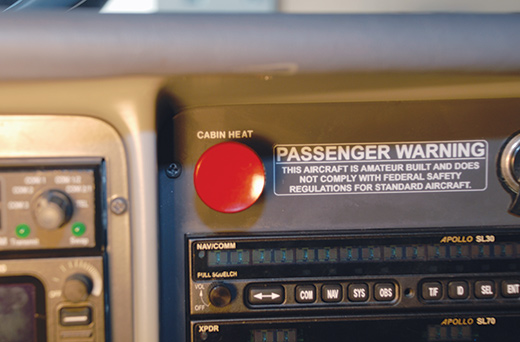
The cabin-heat control should be well marked and located away from the engine controls to avoid confusing it with the carburetor-heat control.
The cabin-heat control should be mounted well away from the engine controls to avoid confusion. It should be clearly marked so that it can be easily distinguished from engine controls such as carburetor heat or mixture. The heater control is usually a ratcheting push/pull control to allow for the fine adjustment of the incoming hot air. The control ends of these solid-wire controls will most likely terminate in a B-nut that clamps down on the wire with a small set screw. The cable sheath can be secured with a Bowden cable clamp or even a small Adel clamp.
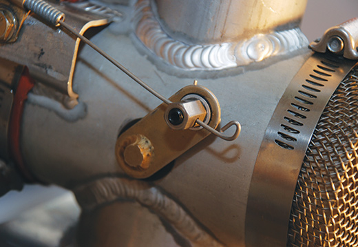
This carburetor-heat valve operates with a solid-wire control cable terminating at a B-nut. Most cabin-heat valves also use a similar arrangement.
Brackets
The engine end of these control cables must be secured by a mount or bracket of some sort. These brackets are not too hard to make yourself, but you can save time by using pre-made brackets that you can buy from Van’s or other kit manufacturers. Even if you’re not building one of their kits, it is worth checking out these sources before going to the trouble of making your own.
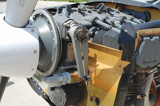
This Sportsman with an IO-390 engine has a front-mounted prop governor. The bracket for the control cable comes from Glasair but could be used for other front-mounted governor installations.
If you decide to make your own brackets, round up the clamps, rod ends and other hardware you plan to use with your control cables. Install as much of this hardware as you can to remove uncertainty from the measurements you will need to take. Then make a mockup bracket out of posterboard. Once you are happy with the mockup, use it to lay out the actual bracket onto a sheet of 0.050 chrome-moly or mild steel plate. Use bends at the edges to stiffen the bracket and cut out lightening holes to reduce weight. These brackets do not need to be terribly strong, but they do need to be stiff enough to resist flexing and cracking in the high-vibration environment of the engine compartment. When your bracket is complete, be sure to paint it or powder coat it to prevent corrosion.
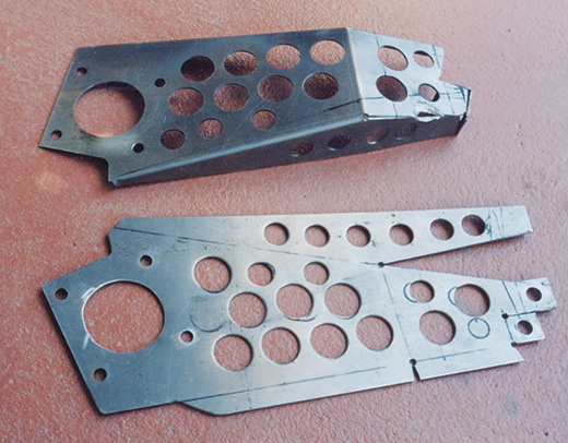
Here an amateur builder is making his own bracket for the throttle and mixture controls. This bracket will attach to the carburetor of a GlaStar. Some stiff paper and tape can be used to make a template that can then be transferred to metal to make the bracket.
A warning: Do not attach brackets to the engine mount or airframe if they will be controlling things that are attached to the engine. Carburetor, fuel-injection and propeller control brackets must be attached to the engine and allowed to move independently of the airframe. Carburetor-heat and cabin-heat controls are normally not attached to the engine, depending on your particular installation. Be sure to check this out before you make your mounting brackets.
When you have finished installing your engine controls, be sure to check them for free and easy movement and sufficient travel. This will likely be one of the first things your DAR will check when inspecting your airplane, and it is very important that it has been done correctly.
When you assemble your controls and attach them to the engine, be sure to use AN363 all-metal lock nuts to attach the brackets and not the more common AN364 nylon insert lock nuts. When attaching controls with rod ends to the carburetor, throttle body or prop governor, be sure to use AN310 castle nuts, cotter pins and AN3-x drilled shank bolts. As a further safety feature, the outside of the rod end should be protected with an oversized washer, just in case the rod end fails.
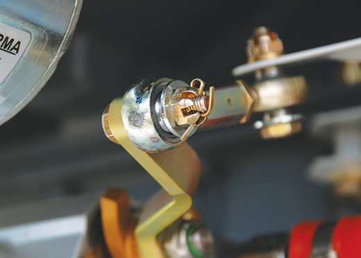
Always use an oversized washer on the outside of any rod-end connections. That way if the rod-end bearing fails, the control will not fall apart completely.
Engine controls are simple, but they are also important, so it is worth spending whatever time is needed to make sure they work well. Next time we’ll take a look at the engine cowl, baffles and intake air.

