 The function of a plenum is to use as little air as possible to cool the engine. This decreases cooling drag, which will increase speed and/or efficiency. But how can you be certain your plenum will work when you’re done and how long will that project take? If everything is ready for the project, it should only take about one week to build.
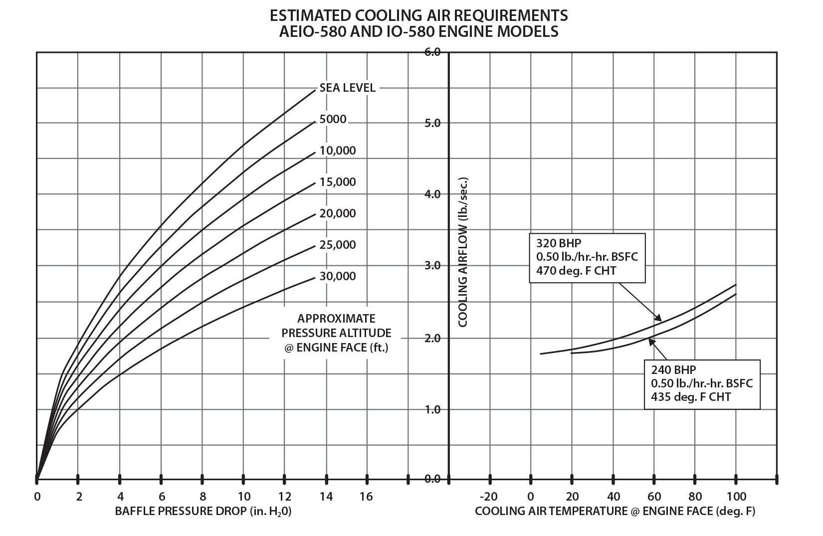
Before you start anything, sit down at your table and calculate the requirements for your plenum, which depend on the engine cooling flow requirements for your mission. Everyone has seen the cooling requirement graphs for engines (Figure 1). These graphs are going to let you know before you start to build anything that your outcome will meet the mission.
If you don’t have access to the manufacturer’s cooling requirements graph, you can look at one for a similar engine with the same single-cylinder displacement. This is not best practice, but if you have a Lycoming 540 with 90-cubic-inch cylinders, it will compare somewhat with the Continental 550 that has 91.67-cubic-inch cylinders. Then you have to take into consideration that both engines produce a similar amount of horsepower per cubic inch.
So, let’s say you are comparing a 260-hp engine to a 310-hp engine; the higher-horsepower engine is producing 50 hp more BTU, so it may require 19.2% more mass flow to cool it. I know this is a very poor way to estimate cooling requirements but it tends to be close.
If your engine produces more than its rated horsepower, it will also produce more than normal BTU output. You will need to divide the horsepower you produce (which can be determined by fuel flow or dyno testing) by the rated horsepower and then multiply that times the pounds/second of air that is required for your engine in the cooling requirements graph.
The Mission
Let’s say we want to be able to take off at an ambient temperature of 100° F and climb at 150 knots IAS and limit the CHT to 425° F with a Lycoming 580-cubic-inch engine. What do you need to do to arrive at that goal for your plenum design? Find 100° F cooling air temperature and 435° F cylinder head temperature on the right side of Figure 2. Then look at the vertical line near the center to see that cooling airflow is about 2.65 pounds per second for the IO-580.
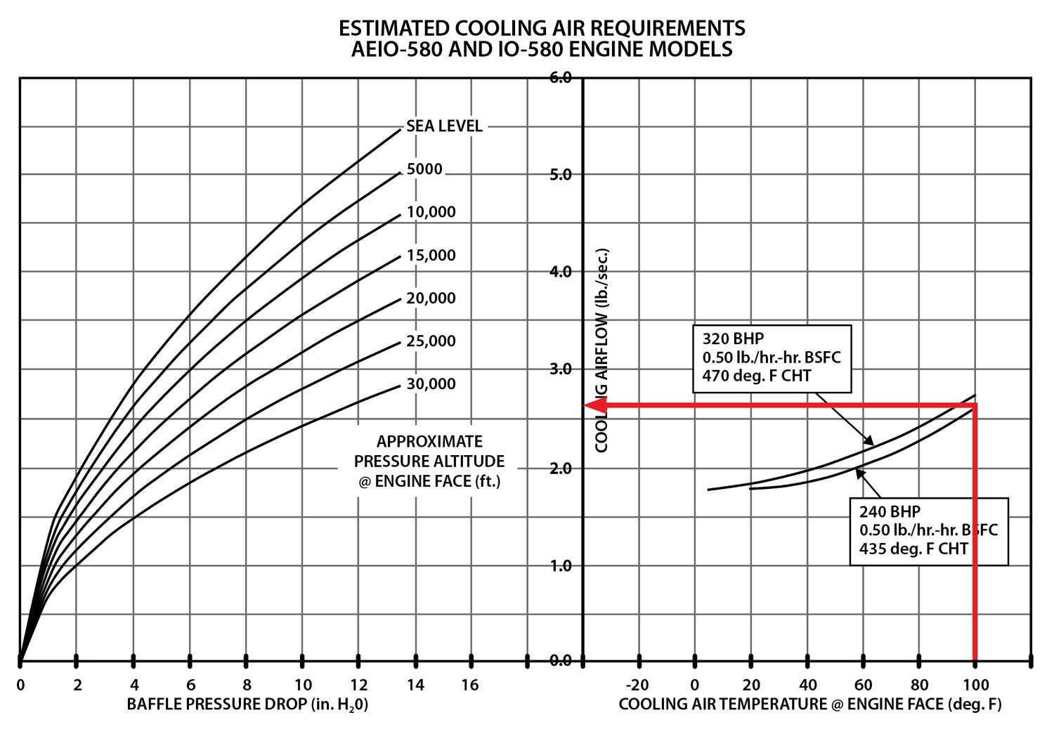
Figure 3 is a graph of the pressure differential that comes directly from my RV-4 data. Anyone can achieve these pressures if they have a smooth inlet, a good diffuser and a sealed plenum. If there is a gap anywhere, seal it, even if you think the fit is good.
At 150 knots you can get about an 11.5-inch water delta p across the cylinders…if you are running good convergence zones or augmenters. Without convergence zones or augmenters you may get about 7 inches of water at 150 knots. The middle line in Figure 3 is from piccolo tubes, which were attached immediately above and below the cylinders that were connected to a Magnehelic test gauge. The top line is from a piccolo tube at the back of the plenum at the case midline. The lower line was from a piccolo tube on the firewall convergence zone about 3 inches above the exhaust. These locations are good enough to predict the delta p possible.
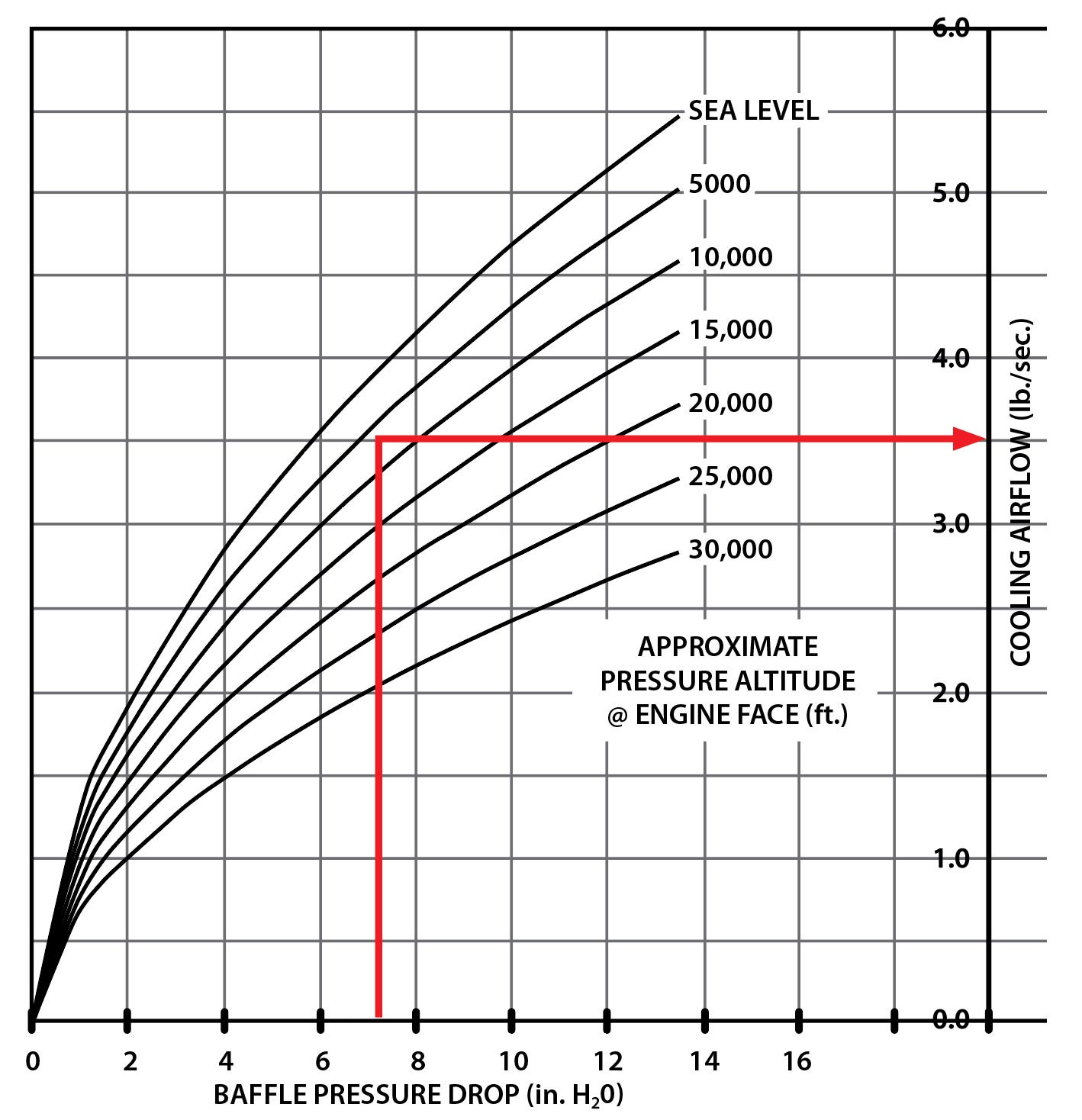
If you don’t have any help decreasing the pressure under the cylinders from your exhaust, your delta p across the cylinders will be around 7 inches of water. As shown in Figure 4, this will only produce about 3.45 pounds per second of airflow. According to the manufacturer’s cooling requirement chart, this should be adequate if you are making every cubic inch of air do its work.
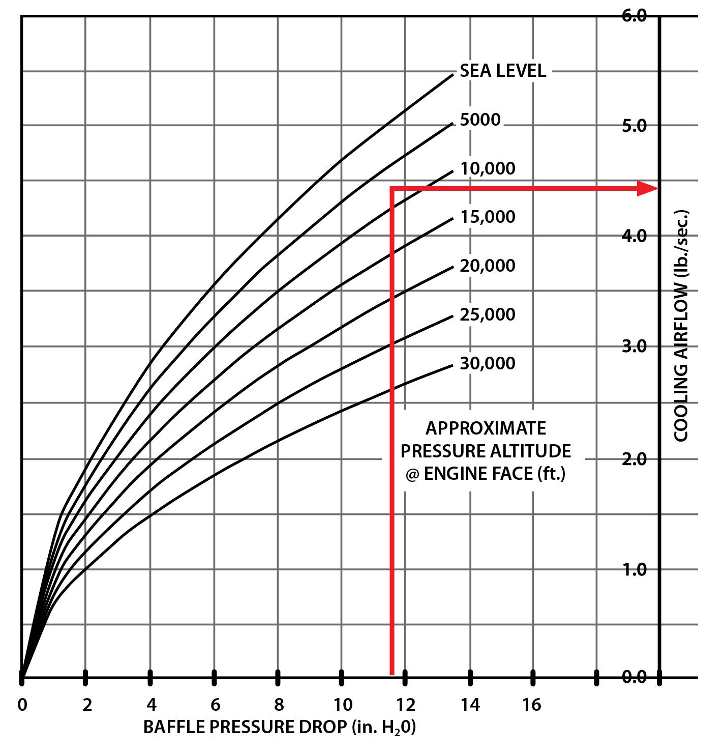
However, with exhaust assistance lowering pressure in the lower plenum, the delta p from immediately above and below the cylinders can be 11.5 inches of water, which would produce about 4.4 pounds per second (Figure 5). This could decrease the potential maximum CHT temperatures during a 150-knot climb with an ambient temperature of 100° F. It could also get the CHTs to around 390° to 400° F with an ambient OAT around 80° to 90° F, but you may have to cool with fuel on extended climbs. Cooling should also increase as you gain altitude, so you’ll have to do some testing to see the actual result.
Sizing the Cooling Inlet To Meet Your Need
Now we know we need 2.65 pounds per second of air mass flow if we want the engine to cool at our planned CHT and 150 knots IAS. So, how big an inlet do we need under those conditions?
1 pound of air = 13.33 cubic feet per pound (standard conditions).
2.65 pounds per second x 13.33 cubic feet per pound = 35.3 cubic feet per second (flow needed for cooling).
35.3 cubic feet per second / (172.5 mph IAS x 5280 feet per second / 3600 seconds per hour) = 0.139 square feet of inlet area.
0.139 square feet x 144 square inches / 0.94 inlet efficiency = 21.3 total square inches.
Total = 21.3 square inches of inlet required at 150 KIAS during climb.
For ease of construction two 3.75-inch-diameter round inlets would amount to 22 square inches. Most configurations with 11 square inches per side will work. Extended climbs may require additional cooling with fuel flow.
Execution
You should use the best inlet shape that decreases inlet losses; this appears to be an elliptical shape. In lieu of an elliptical shape, depending on cowl space or configuration, a generously rounded or airfoil-shaped inlet will work but just not as good, which may result in a little less inlet efficiency.
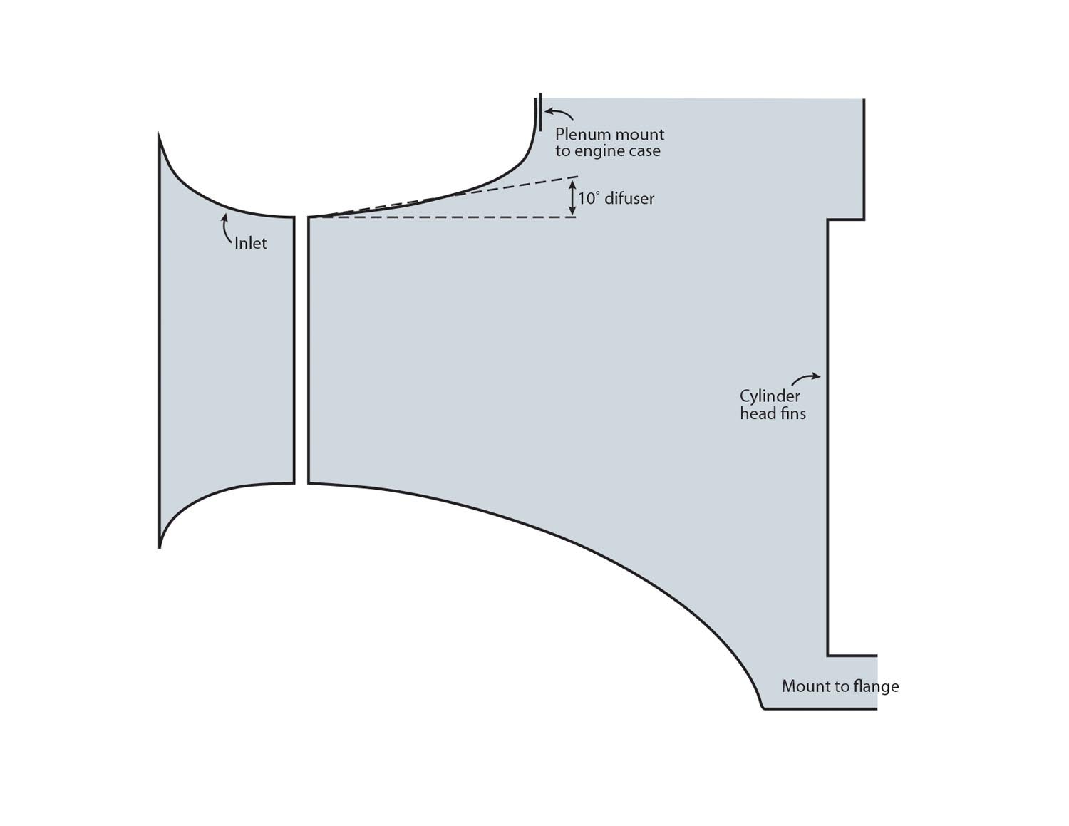
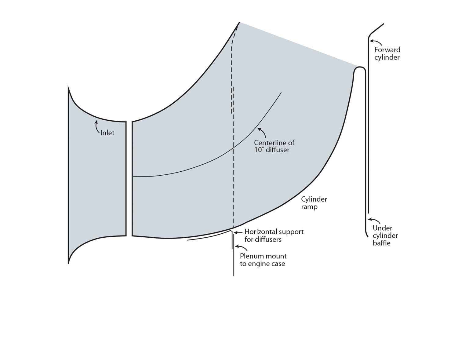
The inlet shape should transition smoothly into a diffuser. The diffuser can be up to around 12°, at which point a planar (flat) diffuser will separate flow. However, the flow in an axisymmetric diffuser may stay attached just a bit longer because it kind of folds in upon itself. This delays flow separation a little, which is what we’re trying to prevent.
Instead, we want to maintain a smooth airflow for as long as possible. This allows the inlet velocity to slow without turbulence, and energy is maintained in the flow.
Aero engineer Dr. Paulo Iscold mentioned that a properly sized inlet of this shape is like an airfoil, and it may lower the pressure at the inlet, further decreasing inlet drag even more. Bernoulli’s principle indicates that as volume expands, velocity decreases and pressure increases. In just 4 inches in a 10° diffuser, the velocity slows 100 mph. It should be the objective of a plenum to transition from high velocity (q) at the inlet to low velocity, high pressure over the cylinders. High pressure is what we want to increase the delta p across the cylinders. We are trying to conserve as much energy from the flow as possible.

You’ve heard this description from me before, but a visual image is very effective to illustrate what we’re trying to do. Imagine a river with no boulders; the water is flowing smooth and fast with greater volume but a lower height across a sandbar. Then start putting in boulders, ledges and curbs, and the level of the flow will rise and the amount of energy in the flow per square foot goes down.
In a river, all the water has to get down the streambed. However, with the airflow in our plenum inlet, the air doesn’t have to flow through. It can back up, spill at the inlet, increase drag and decrease the delta p across the cylinders.
Construction Procedure
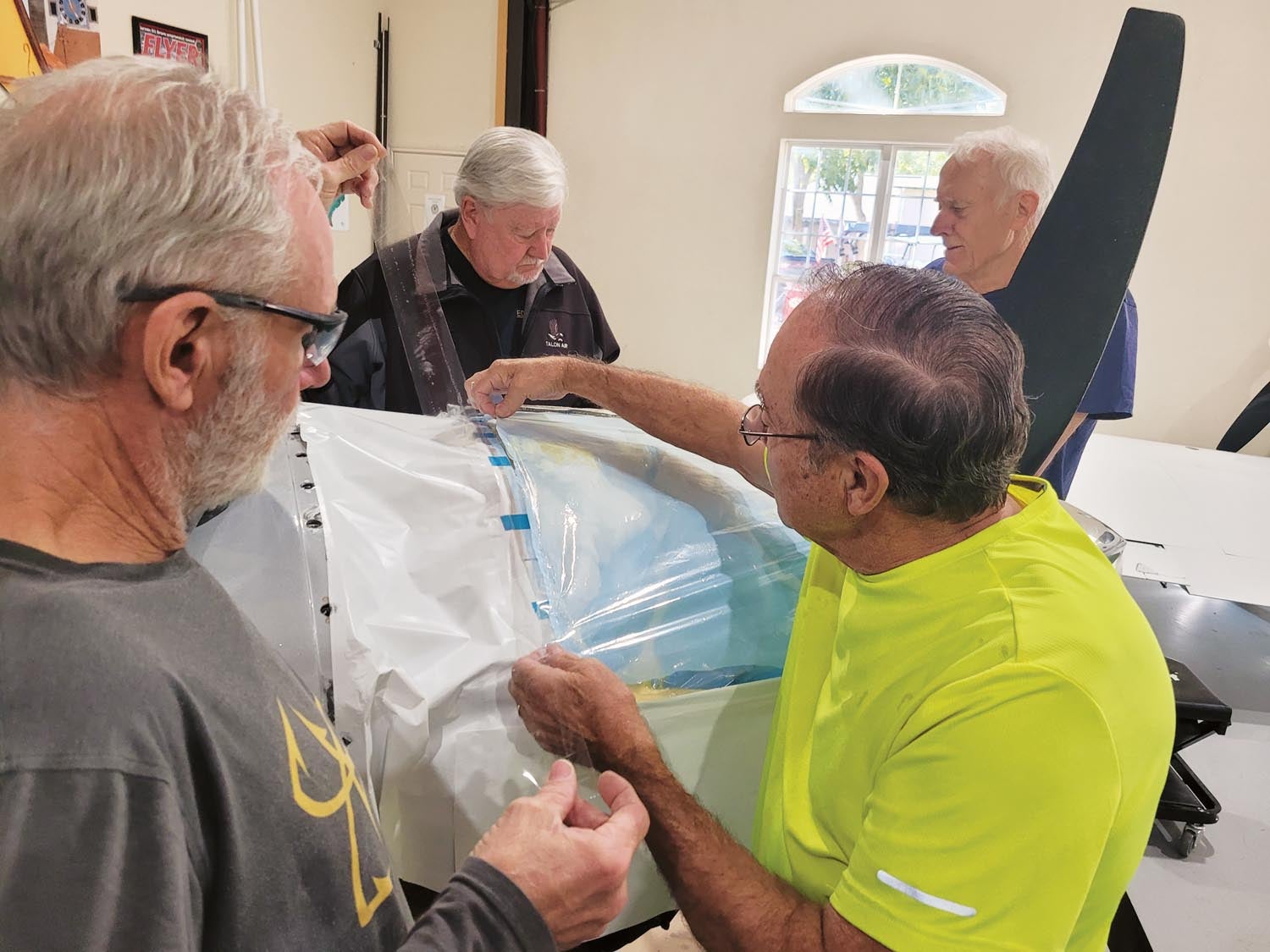
This procedure will work for any air-cooled engine. The plane you see in most of the photos is a Lancair Legacy acquired by Michele Sonier and being worked on by Dick Keyt. Dick is the owner of the Polen Special, which is actually very special due to continued work on his part. A virtually identical plenum was built for Joe Coraggio’s Lancair Legacy. (More about Joe later.)
1. Draw the inlet diffuser and plenum design to scale and determine how the inlets will be positioned, either in the middle of the cowl split line or in the bottom cowl completely.
2. Design and make a mold of the inlet.
3. Determine the mountings for the plenum edges and attach points, and make all the flanges and mounts. Then place them on the engine.
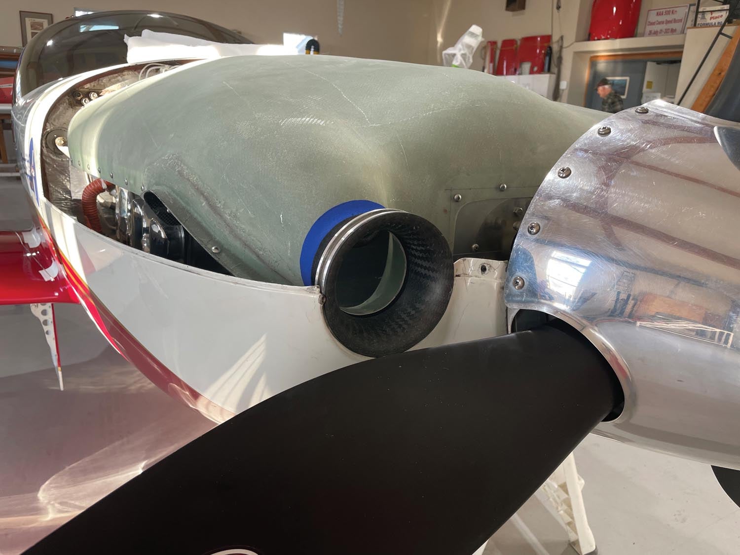
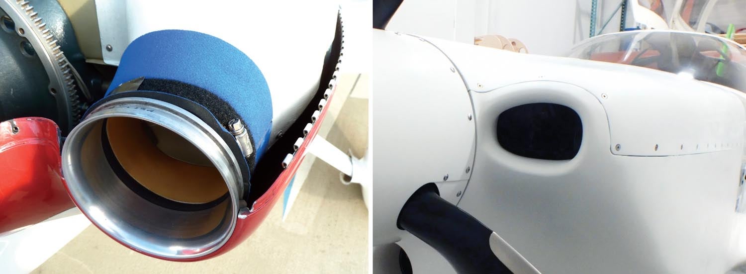
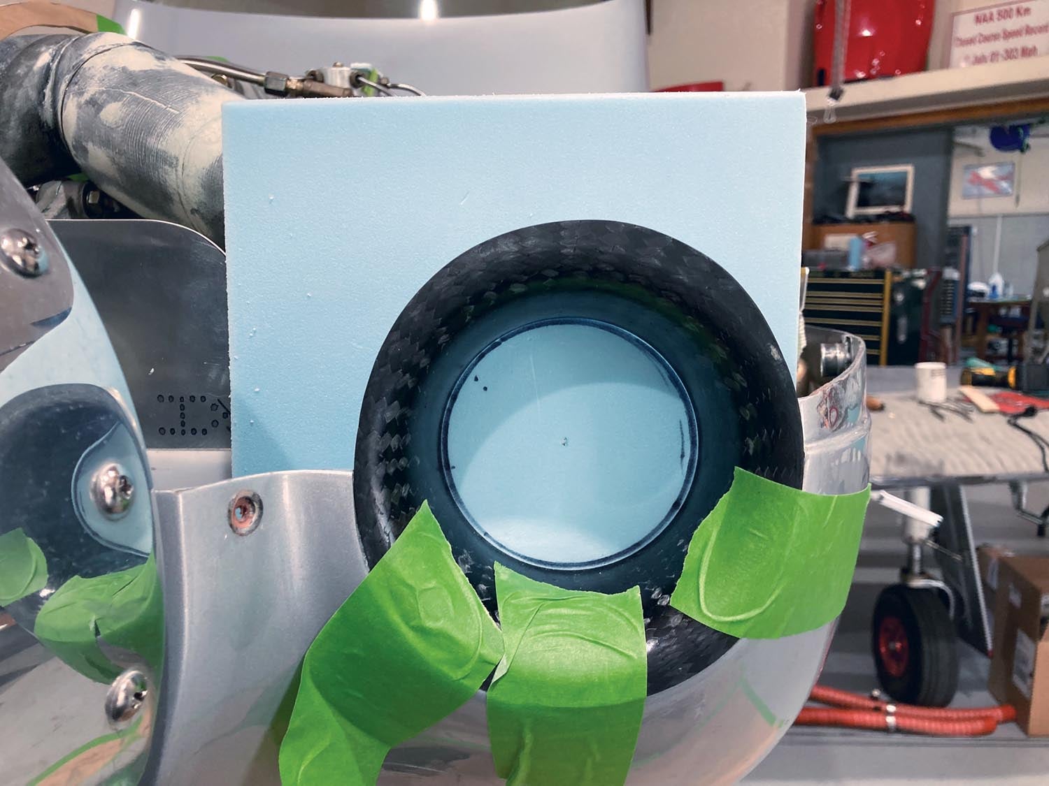
4. Position the inlet and mark the forward position of the plenum opening. The inlet you see below is vacuum bagged carbon fiber tube sock material, and it is positioned according to the cowl inlet position. We used the blue foam, which was hot glued to the forward plenum support bracket, to locate the inlet position for the plenum.
5. Check the cowl clearance. We placed clay pyramids over areas of concern, and the top cowl was put on to determine the clearance inside the cowling. The pyramids that illustrate tight areas can be replaced with a material that when you contact it during contouring, you’re done in that area. The green tape in the photo below has the clearance of each spot written on it.
6. Place the templates for the plenum shapes, and enclose structures that need to live inside the plenum.
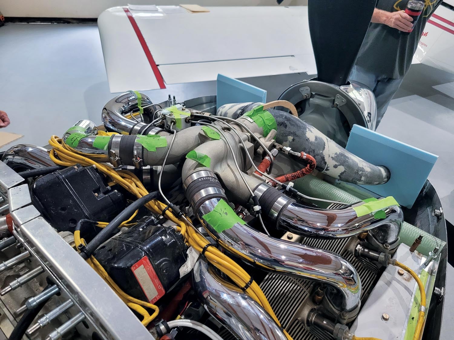
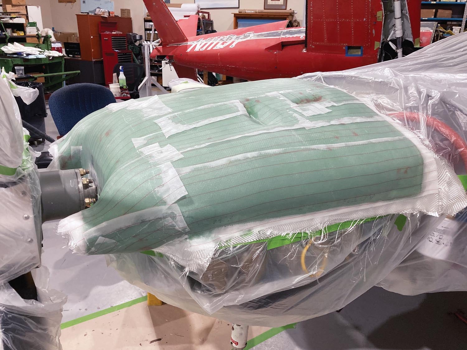
7. The entire engine is bagged from the inside edge of all flanges. Use drop cloths or vacuum bagging material taped to the edges inside of the flanges so it is loose on the engine. It must not perforate! The excess bagging is pushed down around engine components; this bag will prevent any liquid X-30 Expanding Polyurethane Foam from getting on any flange or engine component.
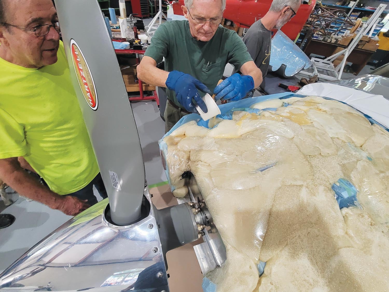
You can control the foam expansion by making a plastic cover above the bag over the engine where you are pouring and by pouring small pours. The foam will try to flow everywhere it can, so be certain your bag has no open corners or edges. By putting plastic or bagging material inside the upper cowl, you can make a pour, place the upper cowl on, then weight it down with a lead bag so the foam won’t push it up. If it is unweighted, it will push!
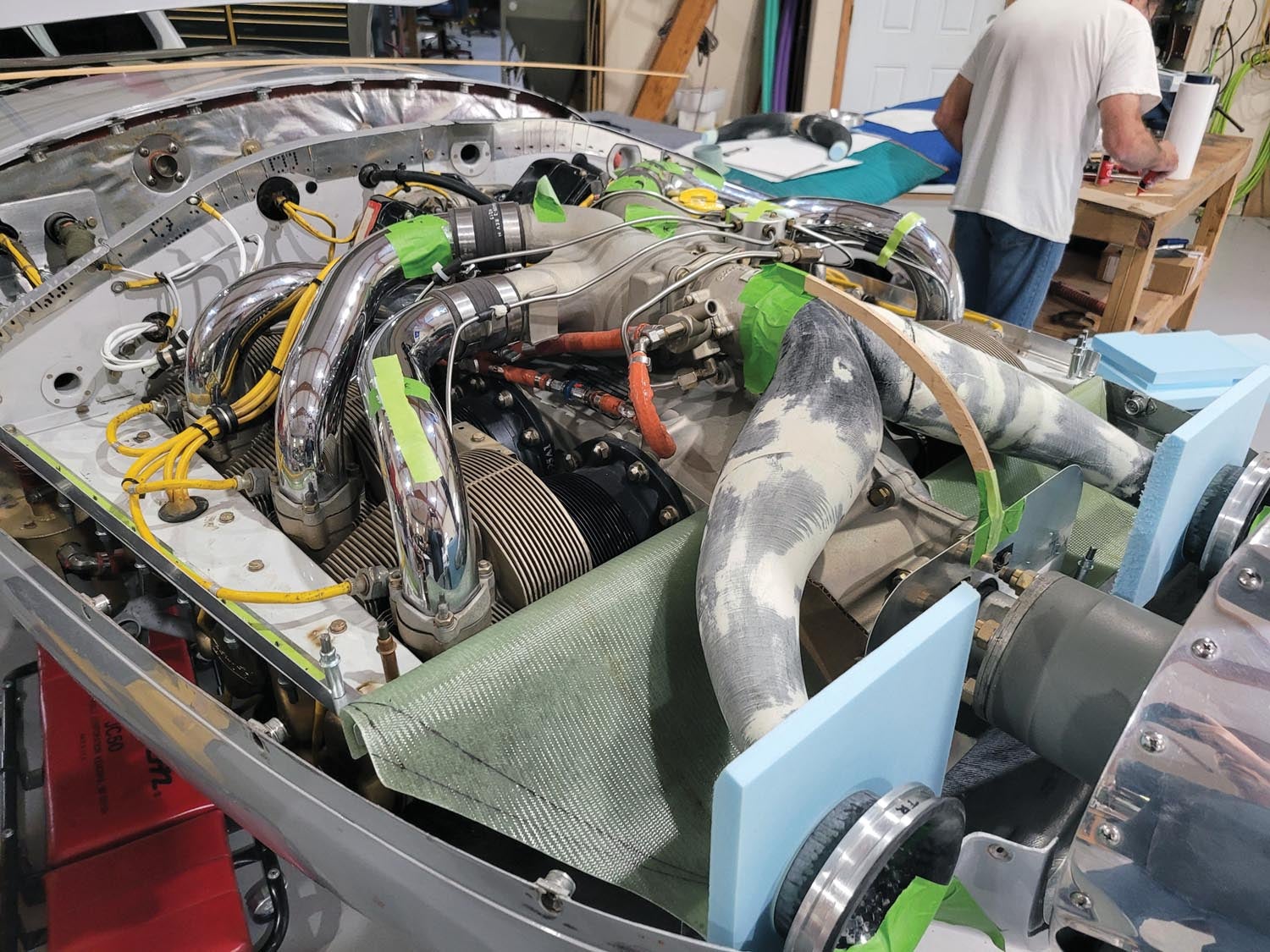
You can leave areas that need custom fitting, such as the blue spot in the lower right corner of the photo above, to a small isolated pour. In this case we needed to have minimum space above and below this area. You can put a single layer of bleeder cloth under the inside cowl bagging material, and the foam will expand and conform to it.
You can make a pour perhaps every 15 minutes; it sets very fast. Plastic does not stick to the pour-in-place foam, and it cuts easier than bread when just using a bread knife. I sand it to the approximate shape with 40-grit sandpaper. It is easy to do!
8. Shape the foam a little to contour and apply lightweight Bondo. Use a curved Surform rasp for the final contour. The rasp will cut the Bondo like a cheese grater, provided the Bondo is at the proper cure, which is just so it doesn’t stick to the rasp when it begins kicking off. The rasp will cut high and low file marks.
File until you arrive at the proper contour. This is based on the templates for the plenum and diffuser angle, as well as the height positions that you want. Sand the high marks to a smooth contour using 60- to 80-grit sandpaper.
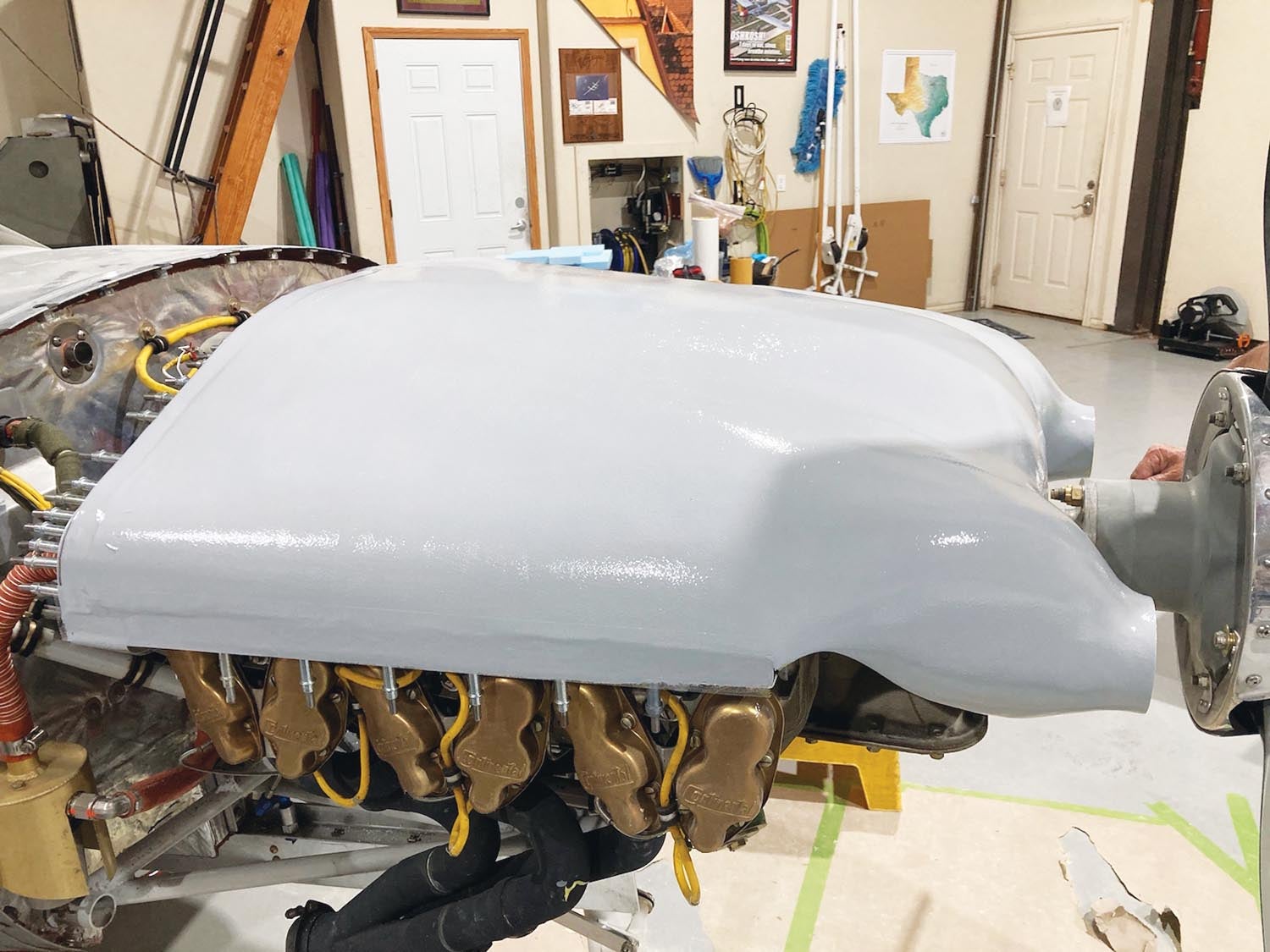
9. Clean off the entire plenum and flanges, then tape off all the flanges entirely. The tape should overlap the Bondo a little. Then roll on hi-fill epoxy or the like, and wet sand the next day until it is smooth. Use spot putty as necessary. Next, apply four to five layers of mold separation wax, then generously coat with PVA.
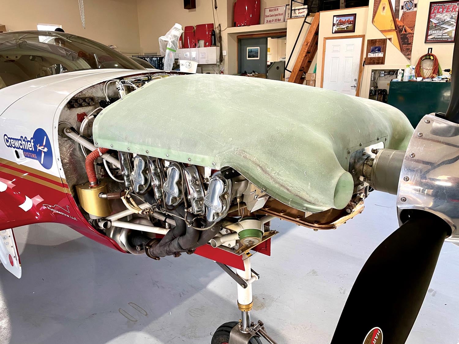
10. Four layers of 8-ounce cloth is enough, and the Rutan-type weave is easy to lay up. I prefer glass instead of carbon, as carbon may produce a ground track for wires lying on it over time. By using pattern templates cut from an old sheet, you can lay this up with only three pieces per layer. I use the small (3-inch) roller technique:
Wet out the surface entirely, then lay on the glass fabric. Be careful to hit the orientation marks on your glass piece as you are placing it. Then use the small, short-nap roller to roll the resin through the glass. If you wipe the roller on the edge of the cup, you can pick up excess resin until you even get pinholes. If it’s drier than you want, just roll on a little wet resin. This technique will provide very good results for wet layups. You can also use peel ply if you like.
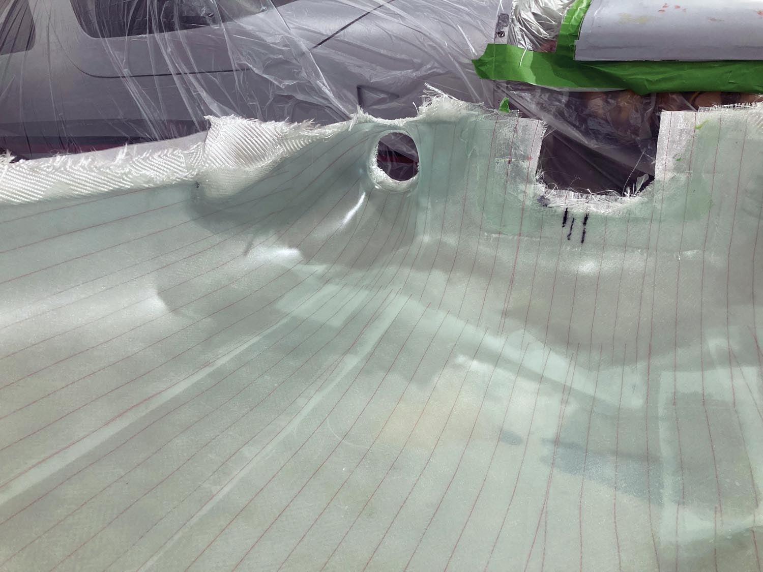
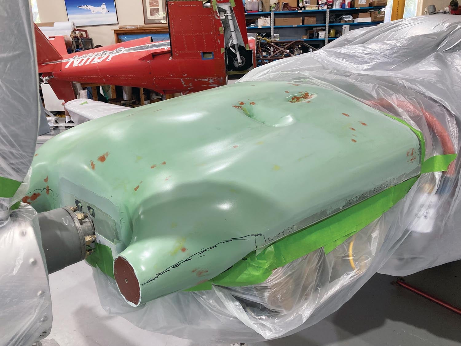
11. The dents on the plenum are for the custom clearances necessary for the oil door mechanism inside the cowl. Just do a small X30 pour there and place the upper cowl on with bleeder cloth under the cowl bagging material. With the cowl over the area of the hinge and mechanism, weight it down so the foam doesn’t push the cowl up.
12. The next task is to trim the plenum to fit and attach it to the engine.
Real-World Results
Joe Coraggio is one of the principal organizers of the AirVenture Cup Race. He also competed in the 430-mile race this year in his Lancair Legacy, equipped with the plenum you see in the last photo.
 We did the calculations for the mission so the plane could run flat out indefinitely, based on his SDS electronic fuel injection and ignition, and not sustain a problematic temperature. This aircraft is being cooled with 19.25 square inches of total inlet for cylinder cooling, engine induction and oil cooling. The OAT during the race was 62.5° to 79° F depending on altitude. Joe is producing around 340 +/- hp at race rpm.
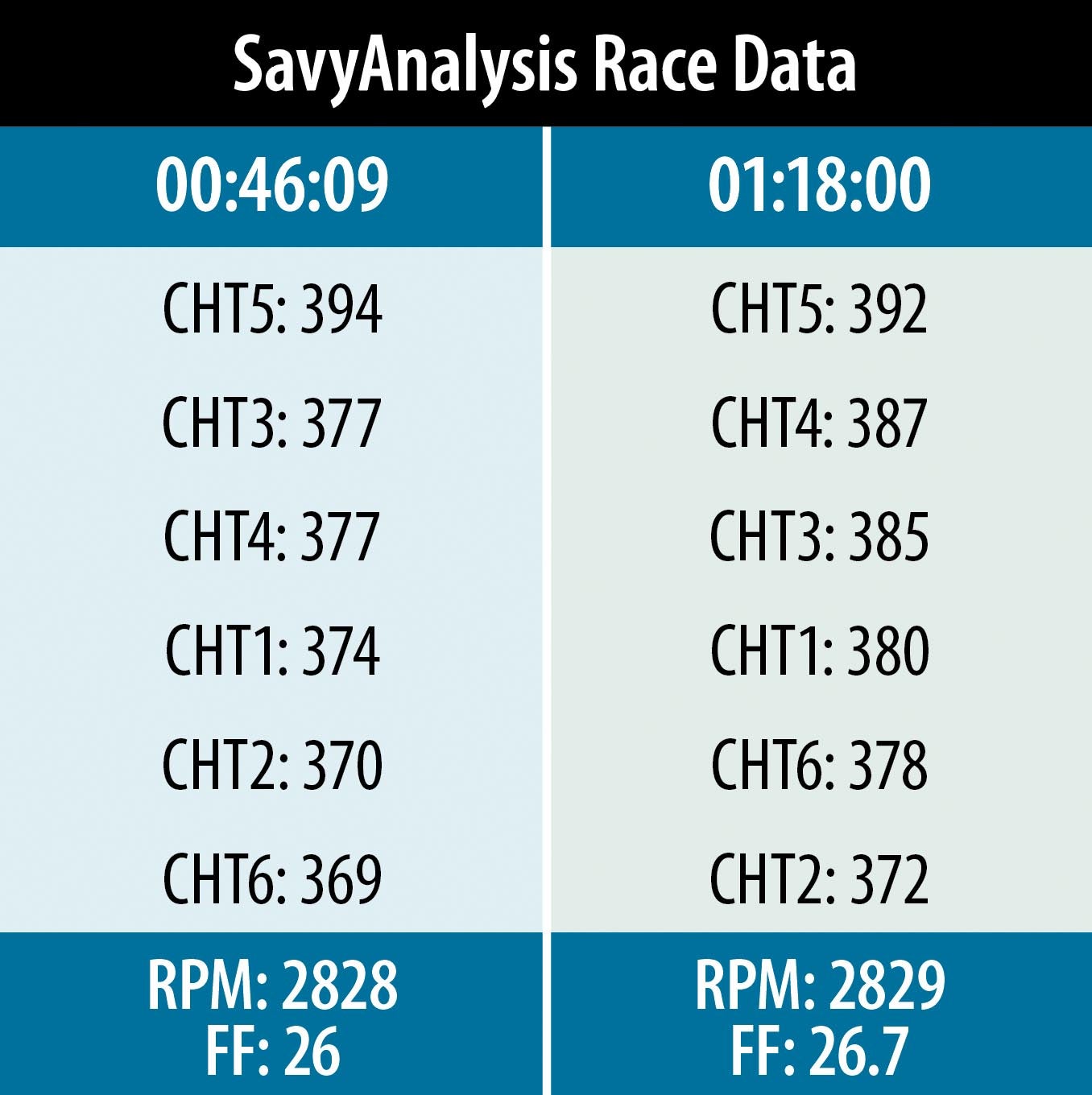
Here is SavvyAnalysis data during the race at 46 minutes and again at 1 hour 18 minutes. The maximum oil temperature was 225° F, and all temperatures were quite stable at +/-5° throughout the race.
So how did Joe place? First in his class.


That was a really excellent article on cooling, thank you for sharing the math through build. Jerry
Any leads on where to get the cooling requirements data you reference?
I’ve searched all over Lycoming’s site, and looked in the Operator’s Manual, and elsewhere on the internet, and can’t find a chart like that.
What am I missing?
I found this via Google. It replicates the Lycoming chart for the (I)O-360 and references the source chart ID – https://www.n91cz.net/Pressure/PlenumPressure.pdf
Comments are closed.