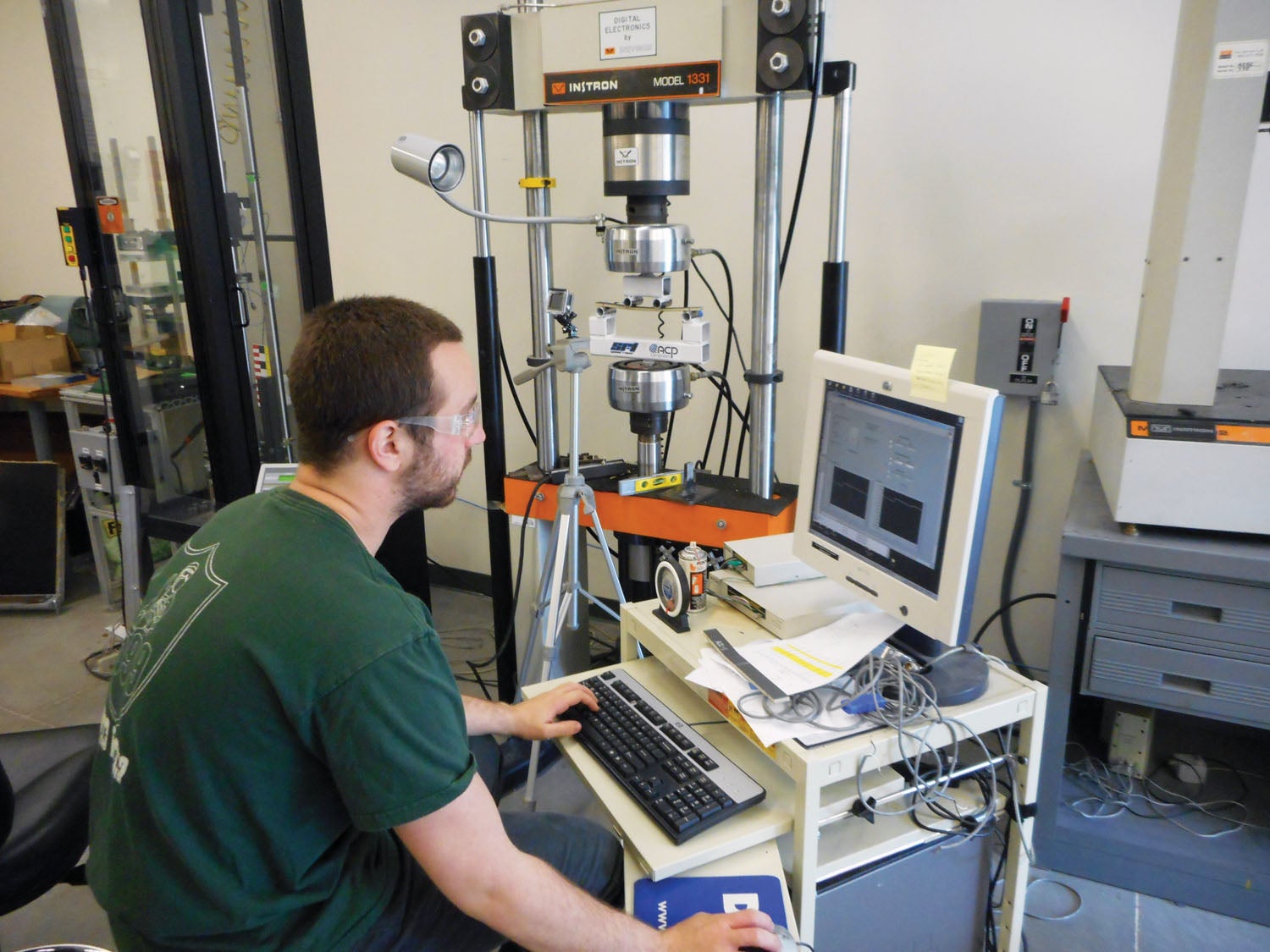
 In Part 1 of this three-part series, we looked at performing a static wing load test to ensure the wing was strong enough for the limit loads prescribed for that plane. The intention of a limit load test is not to break the wing (although that happens sometimes—better on the ground than in the air!). In this article we start breaking stuff—all in the name of making stronger, lighter parts. Meet Thor, a 50 kN universal testing machine (UTM).
Testing Machine Overview
A UTM is a mechanical device that imparts a tensile or compressive load from a crossbar that is raised and lowered by a pair of hydraulic or electromechanical jackscrews. This crossbar is fitted with a load cell, a device that measures force—there’s one inside every digital scale in your shop or house. The UTM software then records this load, as well as the position of the crossbar and the time. Fancier machines may also keep track of things like the number of cycles and elongation of the test piece, known as strain. A variety of parameters can be set when performing a test, such as the rate of speed of the crossbar, maximum allowable load, data acquisition rate and the ability to perform cyclic testing.
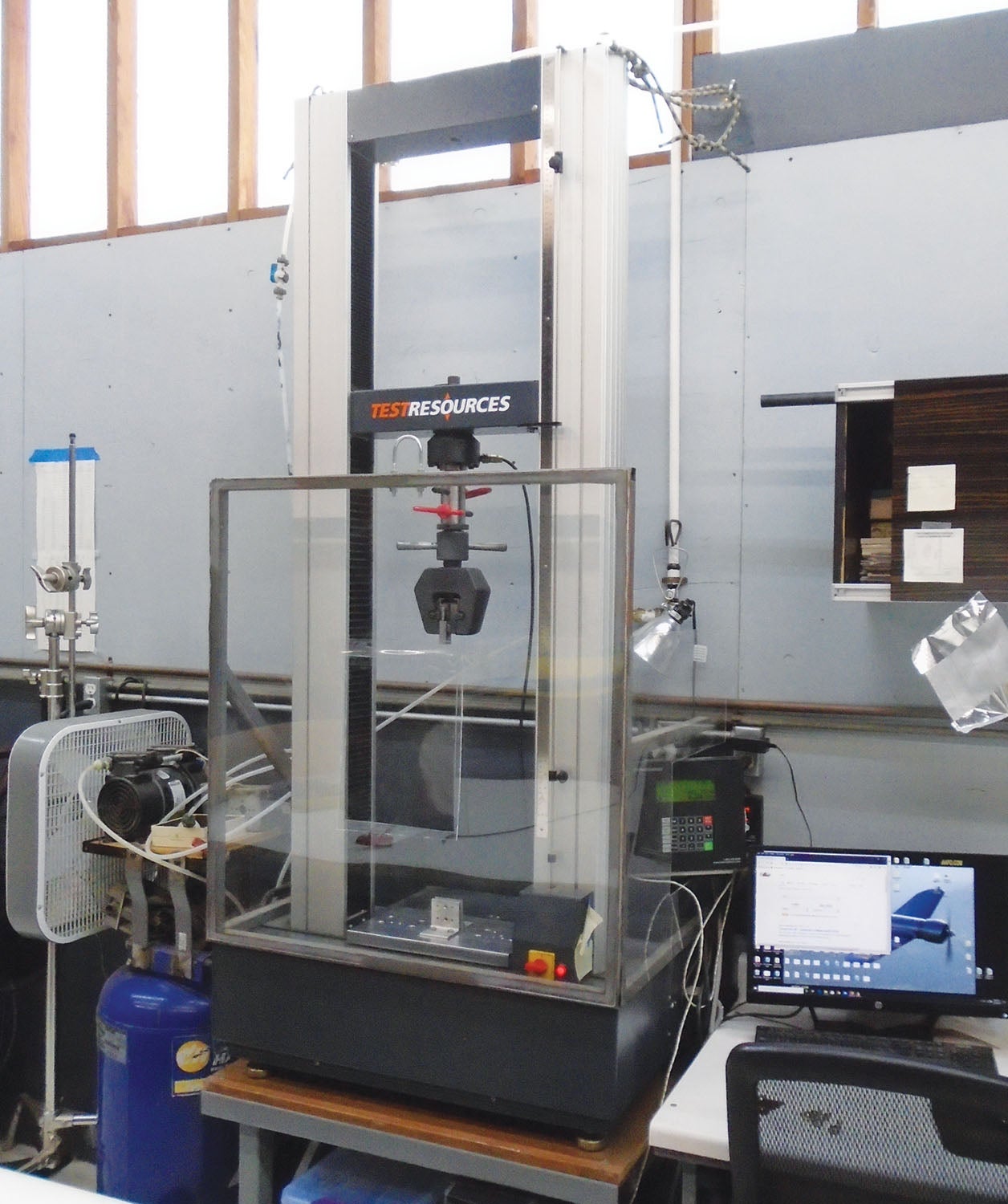
There are a number of companies that make UTMs, but Instron is probably the most well-known, and so you will sometimes hear UTMs eponymously called “Instrons” even though they were manufactured by someone else. Prices are similar to that of a new car. Which new car you ask? Well, you can find new cars for $15,000, and you can find new cars for a heckuva lot more. UTMs are similar, and the more features and higher load capability they have, the more expensive they are. Used units can also be found on eBay and Craigslist, although be sure to find out if the software is still supported.
Would You Like Fixtures With Your Order?
In addition to the UTM, fixtures are required as an interface between the UTM and the coupon or part to be tested. There are literally thousands of test configurations used by engineers to qualify materials, components and finished parts, ranging from metal and plastics to composites and concrete. However, the four basic tests are tensile, compressive, shear and bending strength.
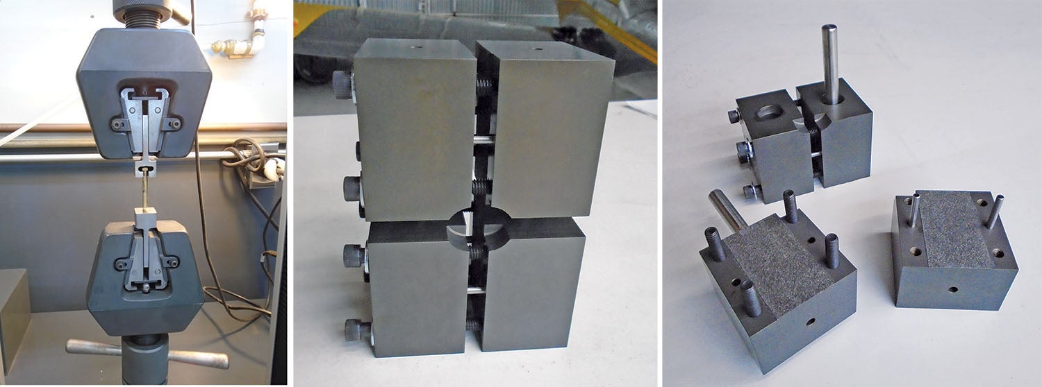
Tensile tests are the easiest to conduct since they basically boil down to grabbing onto something and pulling it apart. Accurate results require that the grips not induce any kind of side loads on the test piece. This is achieved by using some form of universal joint—for example a rod end—at each end of the test piece. Note that in the photo above, the fixture used to hold the bolt does not allow the bolt to do this, so this test, while “quick and dirty,” had limited applicability. In my experience, the greatest amount of time conducting tests is usually spent creating fixtures and setups that ensure the correct application of the load.
Compression tests, on the other hand, are generally the most difficult as the load must be applied perfectly along the axis of the coupon. Unfortunately, both the coupon and the fixtures have a tendency to want to buckle or shift sideways under any appreciable load. As can be seen in the photo of the compression test fixture above, a number of pins, bolts and rods are required to ensure the utmost stability in all axes as load is applied. Still, the coupon itself has a tendency to fail not in pure compression, but rather in non-compressive failure modes like buckling or shearing. For this reason, compression testing is less common.
Shear tests also tend to be challenging and, depending on the type of fixture used, can yield quite different results. Fixtures for shear can be somewhat complicated mechanisms—fortunately I inherited my shear fixture (called an Iosipescu) from engineer Paulo Iscold, whose father machined it during his student days in Brazil. As noted earlier, fixtures can be quite expensive, so machining your own can save a lot of money. I fabricated the four-point bending fixture and compression fixture shown in the pictures as shop class projects.
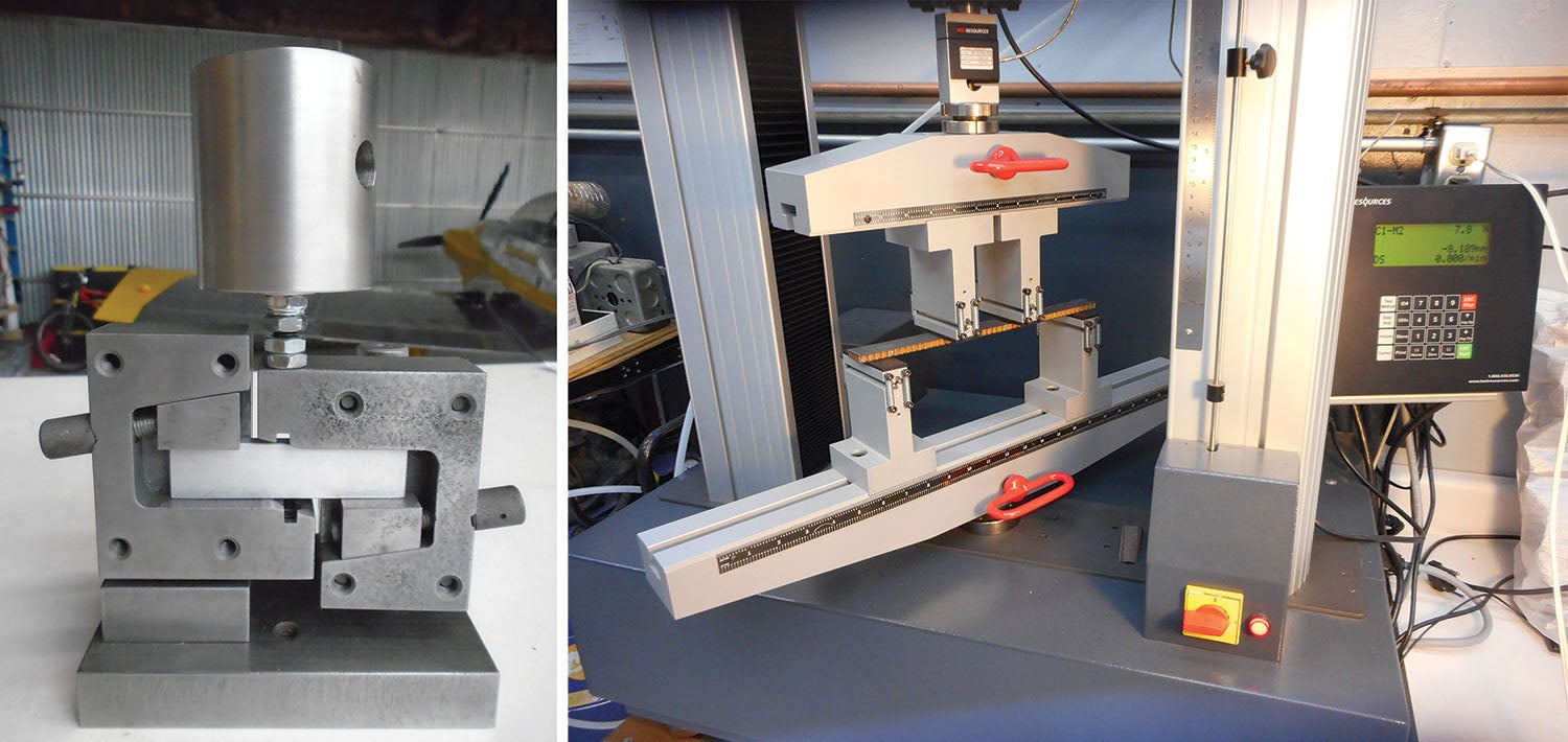
Finally, bending tests subject a coupon to all three of the above forces—imagine a spar for example, with the upper spar cap in compression, the lower cap in tension and the web in shear. As such, bending tests can be used as a proxy measurement for the other three types of tests. Bending tests are typically either three-point (load applied in the center) or four-point (as seen in picture above).
Materials Characterization
The basic fixtures described above are all used for characterizing materials. That is to say, they are used in the early stages of the design process to figure out how strong (or stiff) a material or fabrication process is. Engineers can then use these numbers to perform structural analysis of a design. In the SR-1 Project, we used four-point bending tests to characterize the materials (carbon skins and foam cores) and fabrication processes for the sandwich panels that form the shell of the aircraft.
For example, spread tow carbon fiber fabrics have become prevalent in the past few years (see photos). These are touted as having superior strength due to the flatter weave as compared to traditional weaves: Each over-and-under leads to a crimp in the tow, and the fewer and flatter the crimps, the stronger the fabric.
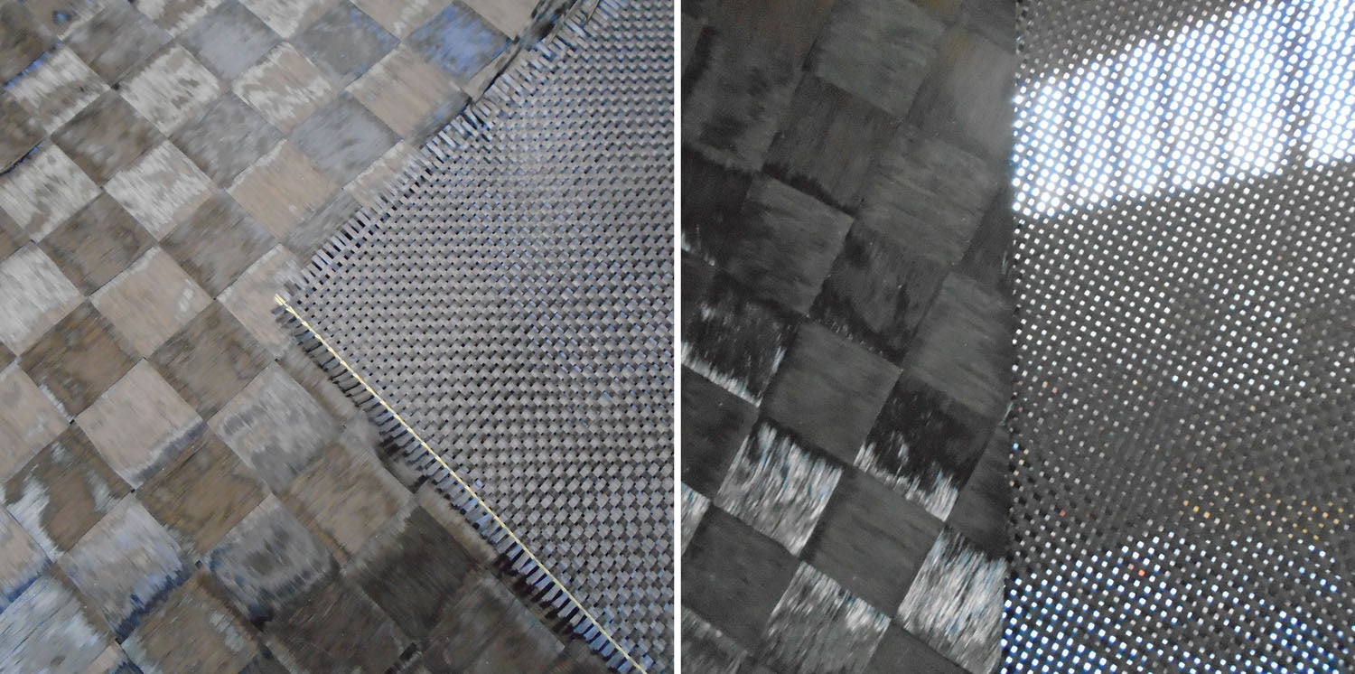
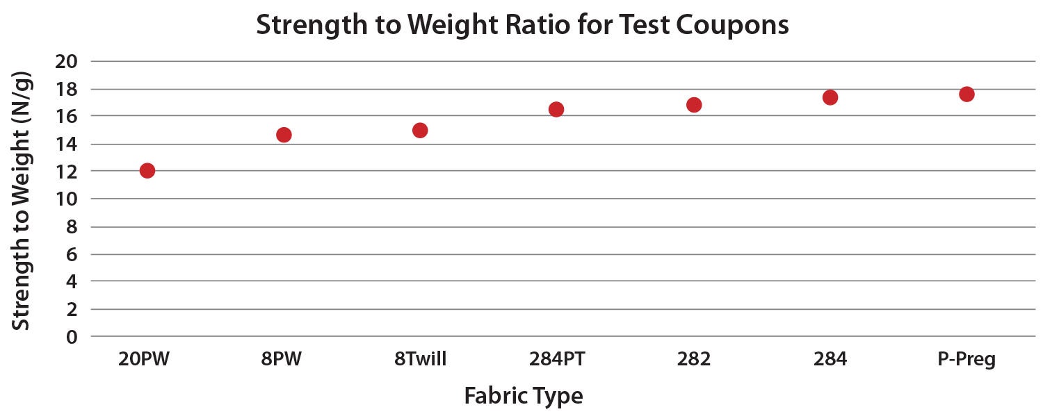
While I do not dispute these claims, when used in the type of wet layup vacuum-bagged panels typical in the SR-1, we actually saw poorer strength-to-weight ratio performance in bending tests of spread tow coupons as compared to traditional weaves (see Figure 1). In addition, because of the exceptionally tight weave of spread tow fabrics, trapped air bubbles under the laminate were problematic and required extra care during layup. So although the spread tow fabrics certainly look cool (there’s no argument that in other industries much of their appeal is aesthetic), the higher price, extra work to remove air bubbles during lamination, lower conformability and lower performance all argued against using them in the SR-1. UTM testing was key in making that decision.
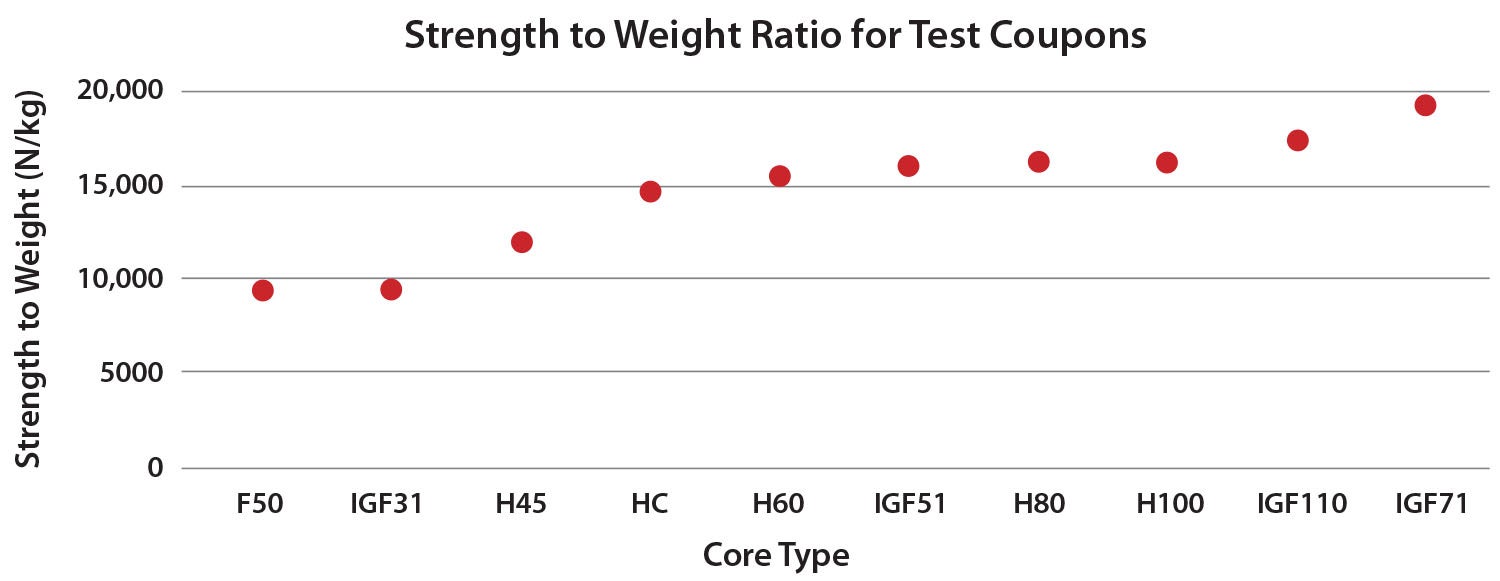
In addition to looking at various types of carbon fiber, the SR-1 Project also used bending tests to examine a variety of foam cores. For example, we looked at different densities of Divinycell PVC and Rohacell PMI foams, as well as honeycomb. Figure 2 shows the strength-to-weight ratio for these coupons. (The ratio itself is meaningless—it simply allows us to see the relative performance of different cores.) For example, it was surprising to see that honeycomb, which is usually acclaimed as the highest performance core available, was in fact only a middling performer. (The reasons for this are beyond the scope of this article, but lie in the layup schedule of the sandwich.)
Tests are useful for qualitative assessments as well. For example, as mentioned above regarding spread tow fabrics, in making the coupons we realized that air bubbles were going to be a concern and also that the fabric was also somewhat stiff and unable to conform to deep curves as well as traditional weaves do. Better to learn this on a test piece than the actual part. Coupon fabrication also gave us an areal weight for sandwich skins, useful in calculating aircraft weight. A derivative calculation, the fiber-to-resin ratio (see my April, May, June and July 2017 articles on coupon testing) is also an important parameter that serves as feedback on the quality of the fabrication process.
Finally, coupon tests reveal potential failure modes. For example, one problem with the foam core tests shown in Figure 2 was that the lighter-density cores would fail in shear before the failure of the carbon laminate. This is an inefficient failure mode and indicates that either a thinner face sheet or stronger core is called for.
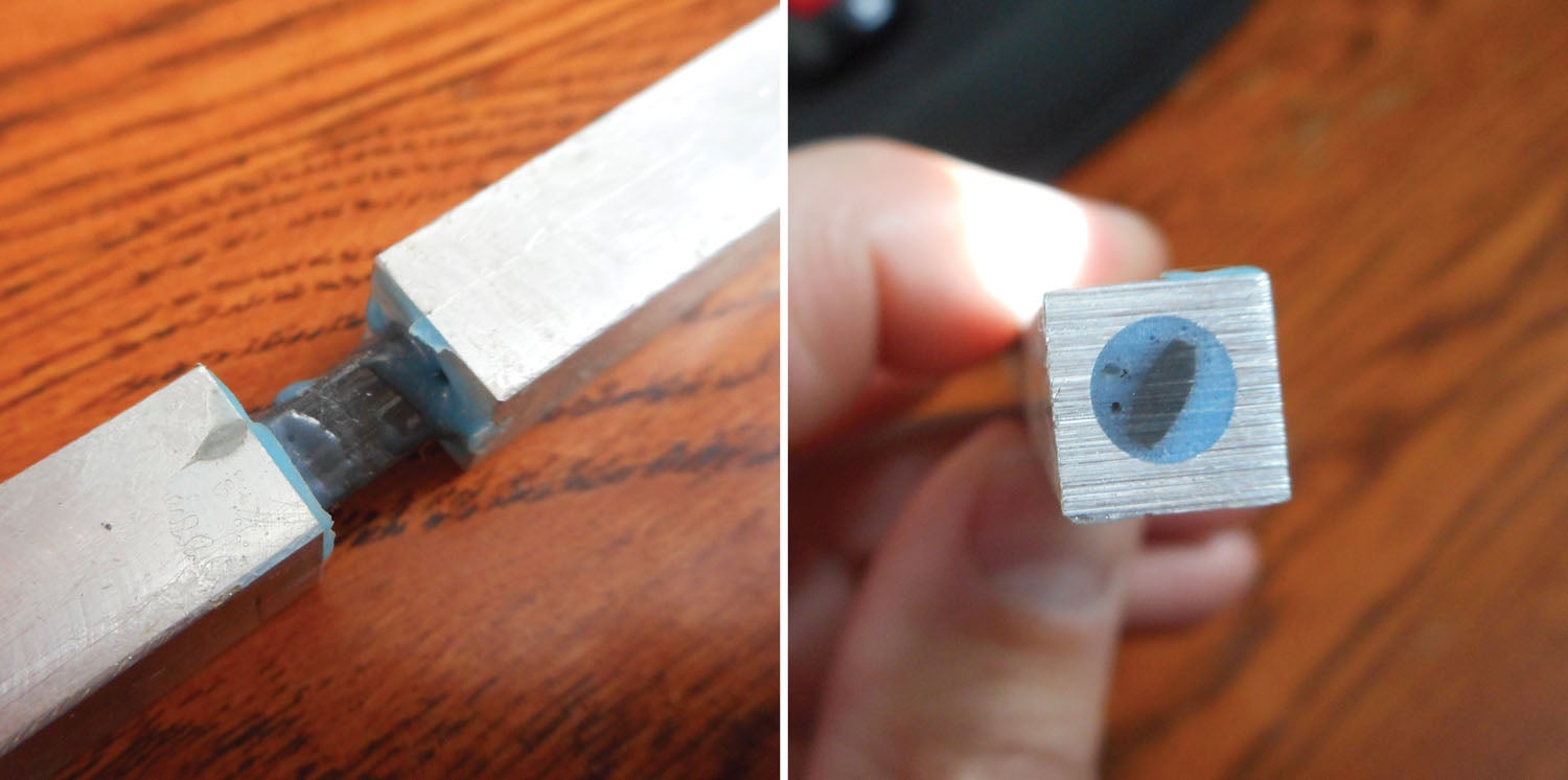
Sometimes, failure modes have to be artificially induced. When testing the strength of aluminum inserts in carbon fiber tubing, the inserts and tubing proved to be stronger than the rod ends used to attach the coupon to the UTM. This was in itself not necessarily a bad thing, since it showed the bonding method was sufficiently strong. However, we also wanted to investigate how adding rivets would affect insert pullout force in the event of a delamination. To model this, the insert was waxed before being bonded and riveted into the tube. Of course, the bond failed at a very low load, after which the rivets took over and we were able to see how much the rivets contributed to the pullout force.
It should be pointed out that many materials will have a technical data sheet (TDS) that provides metrics like tensile or shear strength, modulus of elasticity, etc. And as I’ve mentioned in previous articles, there are a few databases such as the AGATE-NIAR tests that provide materials testing data to the public.
Unfortunately, because composites are by definition an assembly of different materials—for example, fabric (carbon fiber, fiberglass, etc.), matrix (epoxy or polyester) and perhaps core (foam, honeycomb, wood)—there is an almost infinite number of possible combinations of these constituents that exist. Even companies with proprietary databases and expensive composites software have to test. Without testing the exact combination you plan to use, in the form you plan to use it, you are really only making an educated guess (at best) as to how a particular combination will perform. This has been one reason why even though the fantastic nature of composites has been known about for decades, they are only now coming into widespread use in transportation; it costs millions and millions of dollars to characterize these combinations.
Because the SR-1 is fabricated primarily from carbon fiber, the examples I’ve given above have focused on composites. But that is not to say that Experimental aircraft fabricated from aluminum, tubing or other methods can’t benefit from testing—they certainly can and have! But these other fabrication methodologies have been around longer, and their material characteristics are generally more predictable.
That wraps up our discussion on the basics of lab-type testing. Next month, in the final article on testing, we’ll look at using the UTM to test actual airframe components.