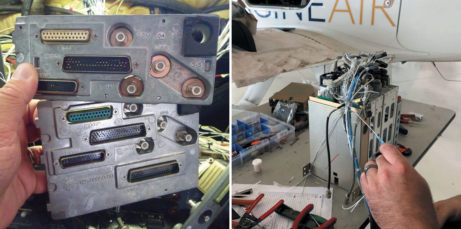
![]() Too many builders underestimate the importance of antenna systems, including working with the signal cable that snakes through the airframe. Cable—including how it’s routed—can make or break the avionics suite’s performance as a whole. So you want to get it right the first time. In this short tech report, we’ll take a look at running the cable and making the antenna connections before closing up the airframe.
Too many builders underestimate the importance of antenna systems, including working with the signal cable that snakes through the airframe. Cable—including how it’s routed—can make or break the avionics suite’s performance as a whole. So you want to get it right the first time. In this short tech report, we’ll take a look at running the cable and making the antenna connections before closing up the airframe.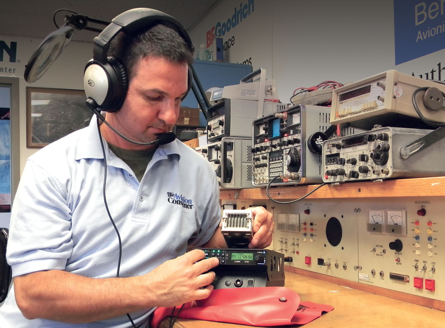
Which Cable?
Follow the lead of the system’s installation manual—carefully. In the bad old days, it was acceptable to wire an entire antenna farm with 50-ohm RG-58 coax, and for some non-critical systems where signal loss isn’t an issue, that still might be the case. But most good avionics techs will recognize that the old black RG-58 cable can have significant signal loss and RF leakage that can degrade or even kill the performance of coexisting systems, including audio panels and even more critical components like magnetometers and GPS receivers. Unwanted noise is often the result of poor shielding at the cable. The jacket material on old RG-58 might be a fire hazard in a crash, which should be a significant consideration. That’s why the majority of installation manuals call for (and suppliers primarily sell) RG-142 or RG-400, which are low loss and have much better (twin) shielding. Also, if your RG-400 and -142 have been sourced from an aircraft supply house, they might have a protective jacket that’s fire-resistant.
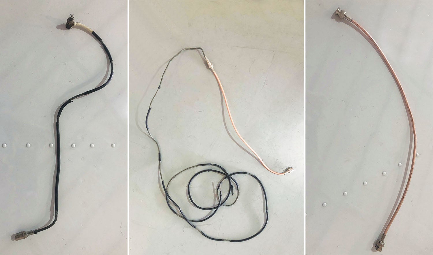
In case you’re wondering, RG-142 and RG-400 are basically similar cables, except that RG-142 has a solid center conductor and RG-400 has a stranded conductor. Solid conductors like the RG-142’s have slightly less loss per foot and the overall cable is lighter, but the stranded-core RG-400 is more flexible and is said to have better resistance to flexing fatigue. Right now, RG-400 is about a dollar a foot less expensive than certified RG-142.
A dull but worthwhile read is the FAA’s advisory circular AC 43.13-1B (specifically, chapter 11), which offers practical guidance and the best practices for selecting the proper cable and connectors, in addition to properly routing them throughout the airframe. And laying in the coax is something you want to do early in the build process because it may not be easy to do well as the project advances. Your back will thank you. Also, when possible, make the connectors easy to access in case you need to move or replace antennas later on. (Because of course you will.)
There’s little room for install error, and even something as simple as a com transceiver should be installed per the manual when it comes to wiring the antenna cable. For instance, eyeballing the installation manual for Garmin’s GTR-series com radio reveals some specifics on antenna cabling. Garmin prescribes that the coax should be RG-142, RG-400 or comparable quality, which is pretty much the standard across the board for Garmin and most other brands of equipment. Which systems need coax? Pretty much anything with an antenna, including VHF com and nav radios, GPS/satellite systems, transponders and an ADS-B system.
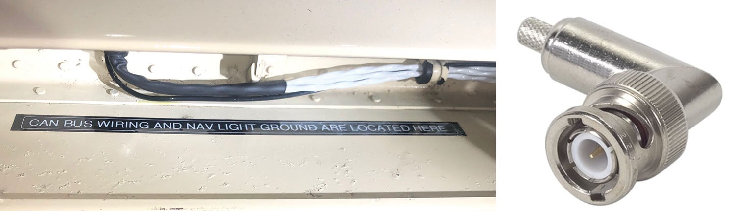
Almost universally, the antenna connectors that join the cable on both ends will be quick-disconnect BNC or thread-on TNC types. Some are available in right-angle form, which could be extremely useful in tight areas. And speaking of tight areas, don’t forget that the body of the connector will need to fit through any bulkhead hole you drill. A typical outside diameter of a TNC body is 0.65 inches, while a bayonet-style BNC might be a touch smaller. Don’t skimp on quality; this hardware isn’t cheap, or at least the high-quality stuff isn’t.
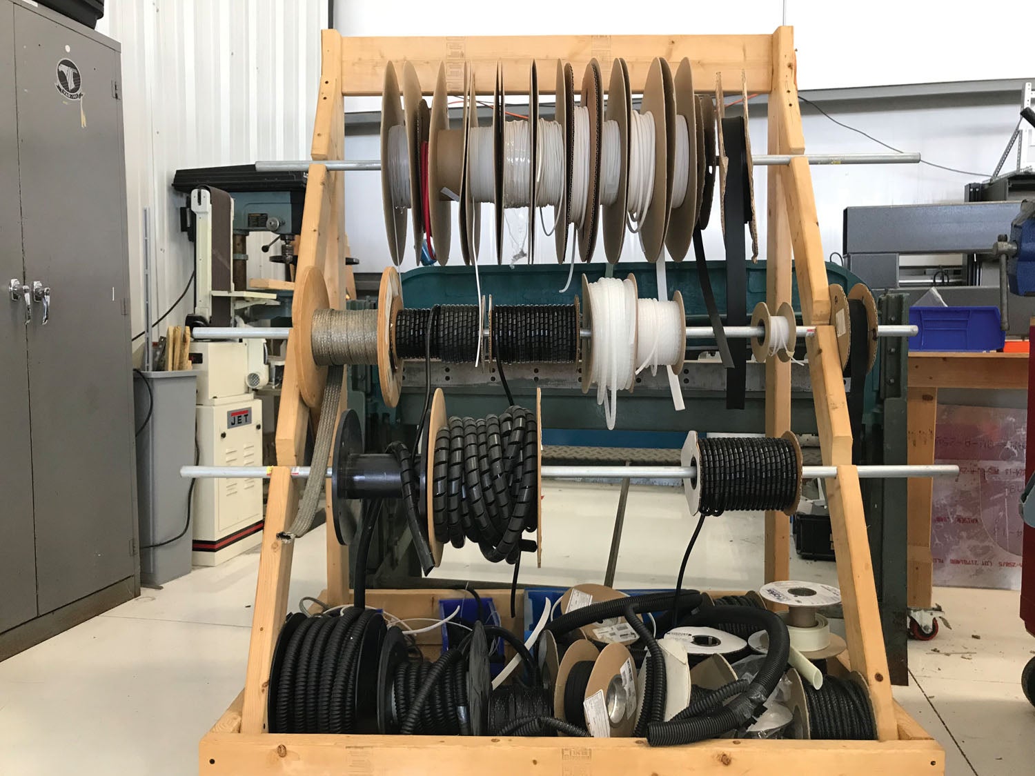
A dual-crimp Amphenol male TNC (a common connector for attaching to the female connector on many WAAS GPS antennas, to name one application) sold through Aircraft Spruce (and plenty of other suppliers) is $20 per connector. You’ll pay dearly for good cable, too. RG-142 typically sells for $5.50 per foot, and many builders find it more efficient to source a roll of, say, 100 feet or even more. Measure out what you’ll need for cable and connectors for all the systems in your kit and take it from there. You could source the cable from an avionics shop, but many won’t be willing to cut 100 feet or more from their bulk supply. Best to have your own raw supply of cable on a spool.
In general, there’s no real limit to cable length, except for systems where loss is a critical factor. For those, you’ll have to do some math to make sure the cable length matches the specs of the equipment configuration. But in general, when you route the cable to the antennas, you’ll want to be as accurate and efficient as possible. Since there is generally no straight-run path between the instrument panel and the antenna, leave enough extra length for bends, but keep the coiling of extra cable to a minimum.
Up at the panel, the coax pigtail lengths (this is the short runs of shielded cable that connect the RF input at the back of the radio to the main run of coax) should be less than 3 inches when practical. And always use caution when routing the cable close to the cabling for other systems, especially GPS. Stay away from strobe light power supplies and even servo, gear and flap motors. Be wary of how audio lines—music inputs, cables to your headsets—cross or are close to high-powered transmission lines, especially the transponder antenna cable.
In keeping with the guidance in AC 43.13-1B, ensure that coaxial (and triaxial) cable is bent at a radius of no less than 6 times the outside diameter of the cable. Plus, use caution when routing in areas where the coax might get damaged. While pretty durable, even the highest-quality coax can get severely damaged without much if any indication.
Got Ground Plane?
If not, you’ll need to build one. For fabric and composite installations, it may not matter how well you routed the cable or crimped the connectors because if there isn’t a sufficient ground plane, performance will likely suffer. That’s true even for non-transmitting antennas like the ones used for GPS navigators and ADS-B position sources. Let’s hit the Garmin manual again for guidance: The one for the G3X Touch
suggests the conductive ground plane for the GPS antenna should have a minimum diameter of 8 inches. While that sounds like plenty, you might not have the area where you want to mount the antenna. Like many antennas, the WAAS antenna is grounded through the mounting hardware and the coaxial antenna connection. The Garmin manual suggests that the mounting hardware (washers and nuts) and doubler plate should make contact with an unpainted grounded surface to ensure proper antenna grounding.
Worth mentioning is that it’s important to have good conductivity between the coaxial shield and the ground plane. You’d think it would, but the bottom of the antenna does not need to make contact with the ground plane because the antenna will capacitively couple to the ground plane beneath the paint or covering.

Sometimes even the best cable and routing practices will result in performance issues, especially on a small airframe with antennas in close proximity. One common issue is GPS receiver blocking from the VHF com. But there are remedies. If there is interference that jams the GPS signal when you transmit, you can install a 1.57452 GHz notch filter on the coax cable as close to the back of the com radio as possible. One choice comes from Garmin, under part number 330-00067-00.
Since routing cable with a BNC or TNC connector on it isn’t always practical, you should learn how to crimp your own connectors so you can do it on the aircraft. For simpler systems, you might have a shop crimp for you. In any case, poor connector crimps will come back to haunt you—or anyone else trying to troubleshoot the system they’re connected to. Like many techs, I prefer crimping to making solder connections. It’s just easier and, done right, lasts forever.
For starters, invest in a decent crimping tool that’s made for RG-142/400 cable (most will also crimp RG-58). Crimping the connector on the cable isn’t difficult, but you get better at it the more you do it. If you haven’t worked with coax and connectors, buy spare connectors in case you botch one—or two. There are plenty of tutorials on YouTube, and a good one right here in this feature. You can also use the install manual as a general reference.
Routing and EMI Considerations
To paraphrase some of the FAA’s guidance, wiring for sensitive circuits that may be affected by EMI (electromagnetic interference) must be routed away from other wiring that can cause signal issues or provided with sufficient shielding (yes, like using twin-shielded coax) to avoid performance-killing interference. Keep in mind that EMI between susceptible wiring and wiring that is a source of EMI increases in proportion to the length of parallel runs and decreases with greater separation. In other words, provide as much physical separation between multiple runs of coax as possible.
Coax should be used with the shield connected to ground at a single point or multiple points, depending on the purpose of the shielding. You can also use a solid airframe ground as an EMI shield. If there’s any doubt, lobby the help from an avionics shop, which should know what might cause trouble in your kit.
Plan It Early
Start planning the antennas and cabling early in the project. As the fuselage begins to take shape, think about how you’ll route the coax, how you’ll provide strain relief and also consider things you can do to easily inspect the cable and connectors as the aircraft ages. The continued airworthiness of antenna systems is important but is often overlooked.
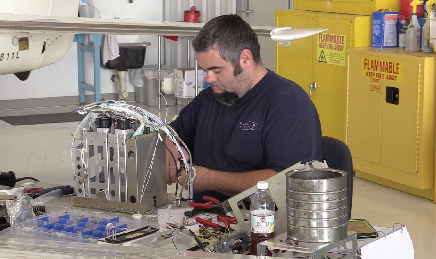
Photos: Larry Anglisano and Marc Cook.
![[Credit: JetStream Rider]](https://www.kitplanes.com/wp-content/uploads/2026/04/AdobeStock_345999332.jpg?w=218&h=150&crop=1 "2026 Avionics and Lights Buyer’s Guide")
![[Credit: Dynon]](https://www.kitplanes.com/wp-content/uploads/2026/04/EMS-stand-alone_HDX.png?w=218&h=150&crop=1 "Dynon Unveils Scalable Engine Monitoring for Kitbuilders")


Another great article to add to my avionics information collection. I’ve been using RG400 almost exclusively my homebuilt but I don’t have any crimp tools. These items are too expensive and too specific for the application. I take my connectors to my avionics shop and get them to put the connector on. The last one was for my ADS-B OUT cable on my EchoUAT which not only required low loss (<1.5dB), but I needed a right angle SMA connection to the antenna.
The issue of VHF transmissions affecting GPS receiver sensitivity is a definite possibility when the two antennae are in close proximity. The siting requirements usually specify at least 2 m (COVID 6ft?) separation. I doubt that a filter would help in the VHF lead in this case as the GPS antenna/amp can't be that good at the price we're paying. Ten watts of VHF is enough to desensitize any very sensitive GPS receiver. Luckily most GPS receivers are now integrated into a single antenna package but a GPS navigator is susceptible to pickup on the RF cables.
Great article with lots to consider during our RV 14A build.
We’re currently finishing up building the wings and planning on installing fiberglass Ziptips with an Archer VOR antenna. The Archer antenna instructions are very good for how to run the forward lighting wires to minimize interference and we have no problem following them. My question is what is the best practice for running the lighting wires for the aft facing strobe and position lights that are located in the rear of the wingtip? It seems my two options are either to run them directly forward attached to the wing tip’s top surface (at least 7 inches above the antenna on the lower skin) or to first route the rear lighting wires inboard to the aluminum wing rib and then forward along the rib to connect with the other forward facing lighting wires.
We certainly appreciate your thoughts.
Comments are closed.