Frontal area is one of the most misunderstood parameters in applied aerodynamics. It is common to read about a designer’s quest to “minimize the frontal area of the airplane to make it low drag.” Similarly, one often sees statements such as, “I raised the top of the canopy 3 inches, so I will fit in the airplane. I know this will increase frontal area and drag, but I need the room.” Both statements imply that the frontal area of the fuselage is a primary determinant of the drag of the airplane. In fact, this is not the case. The designer of the “low frontal area” airplane is likely to end up with a cramped airplane that is not particularly low drag, and the person who fattened his airplane for comfort, if he does it right, will likely find that the performance of the airplane has hardly changed.
Figuring Frontal Area
If frontal area is an unreliable measure of drag, why do people worry about it so much, and why is it considered important? There are several reasons.
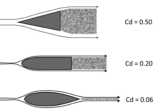
The first is that frontal area is a good parameter for comparing geometrically similar bodies. For example, if I have a body with a frontal area of 1 square foot, and I scale it up to produce a body that is geometrically identical but twice as big, the new double-sized body will have a frontal area of 4 square feet. (Remember that area changes as the square of the linear-dimension scale factor.) The double-sized body will have approximately four times the drag of the original body if they are both at the same airspeed and angle of attack. This direct scaling of drag as a linear function of frontal area only works if the two bodies being compared are essentially identical except for size.
A second reason for the apparent importance of frontal area arises in part from the scaling phenomenon we have just discussed. For non-lifting parts of airplanes such as fuselages, landing gear, tip tanks, etc., frontal area is commonly used as the reference area for the drag coefficient (Cd) of the component.
The drag coefficient (Cd) is defined as the drag of the component divided by the dynamic pressure of the airflow, and also divided by a reference area. It is these drag coefficients that we find in reports describing experimental drag measurements and in tables of drag data. By putting the data in coefficient form, we remove the influence of size and airspeed from the data and make the data describe the characteristics of the shape itself.
As we have seen, for a given non-lifting shape, drag is indeed proportional to frontal area, so it is appropriate to use frontal area as the reference area for the drag coefficient.
Another place where frontal area is commonly used as a metric of drag is the automotive world. Until recently, automobile bodies were all bluff bodies. The airflow separated on the aft portion of the body, and the car generated a large, separated wake as it moved through the air. If a body has a large wake like this, the drag of the wake, called the “base drag” of the body, is much larger than the drag caused by other factors. The base drag of a body is determined by the size of the wake, and for a car-shaped body, the cross-section of the wake has about the same area as the frontal area of the body. (This has changed for the better in recent years, as fuel economy becomes more important.) Under such circumstances, the drag of the body is close to proportional to its frontal area.
In summary, there are some areas where frontal area is a useful parameter. Most people are familiar with automobiles, so the use of frontal area as the reference area for aircraft-body drag coefficients, and the fact that drag is proportional to frontal area for bodies of the same shape but different size, give the impression that frontal area is a primary determinant of drag.
Planes Are Different
In airplane design, there are other parameters about a body that can have effects on the drag of the airplane as great as, or greater than, frontal area.
There are two sources of drag on a non-lifting body. The first of these is skin friction, and the second is base drag caused by separated flow. The airplane designer’s task is to shape the body to prevent flow separation and minimize skin friction.
The aerodynamic drag of ground-based vehicles like cars and trucks is dominated by base drag, which is a phenomenon of separated flow. Unlike ground vehicles, airplanes operate with attached airflow over most, if not all, of their surface. It is this difference that makes frontal area a deceptive parameter to use to estimate airplane drag. The drag of an object with fully attached airflow is almost exclusively skin-friction drag. Skin friction is far more sensitive to the details of the shape of the body than the drag produced by the separated wake of a bluff body. In attached flow, it is possible to have two bodies with the same frontal area and very different drag. If a designer sets minimal frontal area as his goal in an attempt to minimize drag, it is quite possible that he will inadvertently increase the drag of the airplane by shaping the fuselage in a way that decreases frontal area but increases either skin friction or separation.
Wetted Area
The best way to reduce skin-friction drag is to simply reduce the amount of skin rubbing on the air. The amount of skin in contact with the airflow is called the “wetted area” of the airplane. In attached flow, the drag is proportional to wetted area rather than frontal area. A body of revolution with a fineness ratio (length divided by diameter) of 3 has a drag coefficient based on frontal area of about 0.04, if there is no laminar flow. A similar body with a fineness ratio of 7 has a Cd of about 0.06 under the same conditions. If the two bodies have the same frontal area, the body with a fineness ratio of 7 has 1.5 times the drag of the one with a fineness ratio of 3. If we look at it a little differently, the latter body could have 1.5 times the frontal area of the former and yet have the same drag. As we can see from this example, the frontal area alone is a poor indicator of drag.
If the body is designed so that the flow over it remains attached, the drag is determined primarily by wetted area, not frontal area. The large drag difference between the two bodies in the example is primarily caused by the much larger wetted area of the longer high-fineness-ratio body. If our example builder from earlier (the one who pushed the roof up to increase headroom) made his changes properly and the new shape of the canopy does not cause flow separation, he is likely to see little or no measurable change in the performance of the airplane. Although his modification changed frontal area significantly, it probably only increased wetted area slightly.
Flow Separation
Another important factor in the design of a low-drag body is the need to prevent flow separation and keep the air flowing smoothly over the entire body. In the mistaken quest to decrease frontal area, it is not uncommon for a designer to create a shape that causes flow to separate, prompting a large increase in drag. The most common such mistake is a shape that turns sharply aft after going around an engine or the crew. The designer tries to turn the lines of the body aft as quickly as possible to minimize frontal area. Unfortunately, air is not good at turning sharp corners. If the fuselage shape has a sharp break that is not parallel to the airflow, some separation will almost always occur. If the corner angle is shallow enough, the flow will separate at the corner and then reattach further downstream.
This separation bubble causes drag and thickens the boundary layer. It also increases the chance that the flow will separate prematurely somewhere downstream of the bubble. The separation bubble will cause some drag increase. If the break angle is relatively small and the flow does reattach, this drag penalty may be relatively small.
If the corner angle is too large, or the radius of the corner too tight, the flow will separate completely at the corner and not reattach aft of the break, which will cause large amounts of drag. In addition, any tail surfaces mounted aft of the break are likely to experience either blanketing or buffeting.
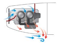
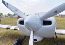
Two areas where sharp corners and separation are common are engine cowlings and windshields. Many light airplanes have engine cowlings with relatively sharp corners between the upper lip of the cooling air inlets and the top of the cowling.
When this cowling is at low angles of attack, the flow is attached. At a higher angle of attack—during the climb, for example—the airflow must turn sharply to follow the tight contour of the upper cowling lip. The flow cannot make this corner, and separation on the upper portion of the cowling results. This problem can be solved by re-contouring the upper lip of the cowl to give it a larger radius and soften the corner the air must turn to get from the lip to the cowl top. Moving the inlets down can help make this easier.
The junction between the windshield and the top of the canopy or cabin can be a troublesome area for separation. It is not uncommon to use a flat-wrapped windshield for ease of construction and to prevent optical distortion. Unfortunately, a flat-wrapped windshield cannot be joined to a flat-wrapped cabin roof without forming a sharp corner. If a compound curved fairing at the top of the windshield is not used to guide the flow around the corner between the windshield and the roof, the flow will separate at the corner.
The top of the windshield and the angle of the windshield are set by visibility considerations. For the contour of the fuselage to curve smoothly from this point aft, the top of the cabin must be some distance above the top of the windshield. A cabin with a lower roof would cause the airplane to have less frontal area, but the sharp corner between the windshield and the cabin top would cause separation and a significant increase in drag, despite the decrease in frontal area.
In summary, frontal area is a useful parameter for comparing the drag of objects of approximately the same shape. Reducing the frontal area of a body by making it smaller, while keeping its shape the same, does indeed reduce drag. Thus, frontal area is useful in sizing wheel fairings and similar bodies. Reshaping the fuselage of an airplane specifically to reduce frontal area will often increase, rather than decrease, the drag. The fuselage designer should pay attention primarily to minimizing wetted area rather than frontal area and should be careful to avoid shapes that can cause separation.

