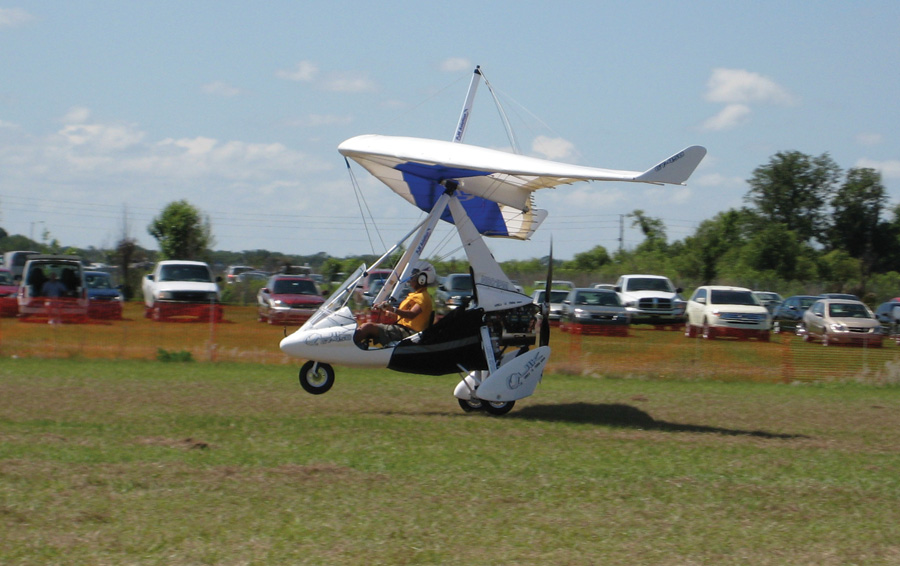
Trikes consist of a cart or pod that carries the pilot (and sometimes a passenger), the landing gear, and a pusher engine suspended under a hang-glider-like wing mounted to a mast on the cart.
Last month, we looked at some nonlinear pitch behavior sometimes seen in conventional airplanes. This month, we turn our attention to a very different, and inherently nonlinear type of flying machine: the trike.
Trikes have become a popular form of Light Sport aircraft. Trikes, which evolved from hang gliders, consist of a cart or pod that carries the pilot and (sometimes) passenger, the landing gear, and a pusher engine suspended under a hang-glider-like wing mounted to a mast on the cart.
One reason for trikes’ popularity is that the wing can be folded like a hang glider. This ability to fold, combined with the fact that the “cart” or pod is quite compact compared to the fuselage of a conventional airplane, makes it possible to store the trike in a relatively small space. It also makes it much easier to trailer.
Control
For this discussion, we will focus on the longitudinal (pitch axis) characteristics of the aircraft. The stability and control characteristics of trikes are very different than those of conventional airplanes. A conventional airplane is controlled by deflecting control surfaces. The control deflection changes the shape of the airplane, which changes the aerodynamic forces and moments generated by the airflow.
Trikes have no aerodynamic control surfaces. They are controlled by tilting the wing relative to the cart by pushing or pulling on a control bar attached to the wing. This changes the angle between the wing and the mast, and swings the pod forward or aft relative to the wing. Pushing the bar forward swings the pod aft. This moves the CG aft and causes the vehicle to trim at a higher angle of attack. Pulling the bar in moves the CG forward, and reduces the trimmed angle of attack.
Figure 1 shows pitching moment vs. angle of attack for an example trike for three different control bar angles. Figure 2 shows pitching moment vs. airspeed for the same machine.
Looking first at Figure 1, we can see that the curves cross at zero angle of attack, which for this example vehicle is also zero lift. What this means is that changing the bar angle has no effect on pitching moment in this condition.
It is very important to understand that the ability to control the trike is dependent on the wing lift. The pitching moment to control the trike comes from the interaction between the lift of the wing and the weight of the pod acting in opposite directions. At zero lift, the pilot has no way of changing the pitching moment. The lift is zero, and the aircraft is in free fall, so the pod is functionally weightless. Both of the forces that act together to pitch the vehicle are zero, so changing the relationship between the CG and the wing does nothing. While the pilot of a conventional airplane can raise the nose by deflecting elevators to produce an aerodynamic down force on the tail, a trike pilot cannot.
Looking at angles of attack below zero lift on the figure, we can see another very important difference between trikes and conventional airplanes. At negative lift, the pitch control effect of moving the control bar is reversed. Pulling the bar in, which would be a nose-down input at positive lift, gives a nose-up (in vehicle axes) moment, and more importantly, pushing out, which will raise the nose and increase angle of attack at positive lift, causes the nose to drop and decreases angle of attack further.
This is potentially quite dangerous since the pilot will likely not be aware of the control reversal. There have been several hang glider accidents during attempted aerobatics where the glider “tucks under” and either tumbles or the pilot falls into the wing. Trikes are susceptible to the same issue.
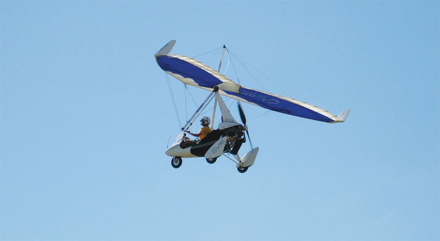
Unlike conventional aircraft, trikes have no aerodynamic control surfaces. They are controlled by tilting the wing relative to the cart by pushing or pulling on a control bar attached to the wing.
It’s easy to see how the pilot will tend to think of the pod he is riding in as inertially fixed. He will perceive his inputs to the control bar as changing the angle of attack of the wing directly, and hence will think “push out for more lift, pull in for less.” In fact, what is really happening is that the control bar input is moving the pod fore and aft relative to the wing rather than controlling wing angle of attack directly.
When the wing is making positive lift, pushing out on the bar moves the pod aft, moving the CG aft relative to the wing. The nose-up couple caused by moving the CG aft causes the vehicle to rotate nose up to a new trim point at higher angle of attack. At negative lift, if the CG is aft of the wing’s aerodynamic center, the wing lift will tend to cause a nose-down rotation about the CG.
The danger here is that the pilot, feeling the wing unload in a down gust, or after too aggressive a pull on the bar, will instinctively push out to restore positive lift. If there is still some positive lift, this will work. If the wing is already pushing down, the push-out on the bar will drive the vehicle to a more negative angle of attack, and it is likely to tuck under uncontrollably.
A properly designed trike wing has an aerodynamic feature that helps alleviate this problem and makes the vehicle safer to fly. Turning once again to Figure 1, note that the pitching moment at zero angle of attack is positive (nose-up). A safe trike or hang glider wing is deliberately designed to have a nose-up pitching moment at zero lift, so the system will self-recover from a zero or slightly negative lift angle of attack if the pilot simply holds the control bar steady and doesn’t push out abruptly. For hang gliders, this characteristic is commonly called being “pitch positive.”
Stability
As we saw last month, the pitching moment of a well-designed conventional airplane varies linearly, or nearly so, with angle of attack. The airplane’s stability is the same over its entire pre-stall range of angle of attack.
This is not the case for trikes because of the large vertical offset between the center of gravity and the aerodynamic center of the wing. The pod of a trike, which comprises a majority of the mass of the machine, is suspended well below the wing by the mast. Since moving the CG fore and aft by swinging the pod relative to the wing is how the trike is controlled in pitch, this vertical offset is necessary to provide control authority.
The vertical offset also causes relative movement of the CG and the aerodynamic center when the bar is held at a constant angle. If the vehicle pitches up, the CG moves forward relative to the aircraft, and if the vehicle pitches down, the CG moves aft. This effect causes the stability of the trike to vary with angle of attack. The machine will be more stable at high angles of attack and less stable at lower angles of attack.
Turning our attention once again to the figures, we can see this effect. Notice in Figure 1 that at all three bar angles, the slope of the pitching moment curve is negative (stable) at the trim point where the pitching moment is zero. Also note that for each bar angle, there is another lower angle of attack where the aircraft becomes unstable.
Figure 2 shows how this effect varies with trimmed airspeed. When the bar is pushed out to trim at lower speed (45 knots in this case), the aircraft is very speed stable around its trim point. Slowing down produces a large nose-down moment, and speeding up produces a large nose-up moment. If the bar is held fixed, the vehicle becomes unstable at speeds above 65 knots. This is not inherently unsafe because the pitching moment at higher speeds is still strongly positive, so the machine will tend to go back to its trimmed speed.
As the bar is pulled in, notice that the level of speed stability (the slope of pitching moment with airspeed) decreases. The faster the trike is trimmed to fly, the less stable it is. This reduction in stability at higher speeds can contribute to the kind of tuck-under loss of control we just discussed since the aircraft will have less natural tendency to stay at its trimmed airspeed. It will also respond more rapidly to a disturbance or pitch input because it is less stable. Our example aircraft can still be flown safely, at least up to the 85 knot speed represented by the lowest curve in Figure 2, because of the pitching moment characteristic of the wing discussed earlier. With a different, poorer, combination of mast height and wing design, it would be possible to end up with a machine that flies comfortable and stably at lower airspeed, and becomes dangerously unstable at higher speeds.
We will discuss the effects of various design parameters on the stability and safety of trikes next month.

![]()
Barnaby Wainfan is a principal aerodynamics engineer for Northrop Grumman’s Advanced Design organization. A private pilot with single engine and glider ratings, Barnaby has been involved in the design of unconventional airplanes including canards, joined wings, flying wings and some too strange to fall into any known category.


