In the December 2019 issue of Kitplanes®, Larry Anglisano took us on a scenic journey of what ADS-B is going to look like from our northern neighbor (“Avionics Boot Camp: ADS-B for Canada and Beyond”). He strongly implied that the rest of the world may just follow Canada’s lead, although for the love of 100LL, I can’t figure out why. The Aireon system using the Iridium series of satellites is totally incompatible with the FAA system, and the Aireon system does not include data link weather or traffic, and it requires two antennas, one on top of the airplane looking at the sky and another one on the bottom of the airplane looking at the ground. To me that just seems like more equipment for less capability.
The comment was also made that the electronic equipment itself is quite a bit more expensive than the USA’s ground-based system, and I’m not all that shot up about our reliance on equipment that is impossible to fix while it orbits the earth some 500 miles up.


So, for the first time in my 35 years of writing this column1, I’m going to give you a design that may or may not work for both USA and “other” systems. Maybe yes, maybe no, but at least I’m going to give my best shot at giving you something to try. Understand that I know the device will work as designed, but whether or not it is compatible with other systems is nothing I can swear to.
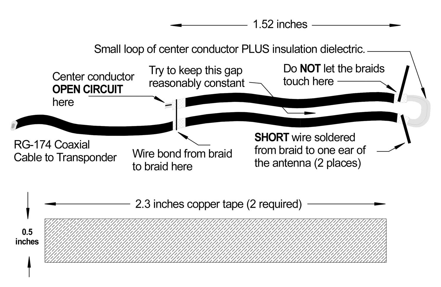
What I am going to show you is an antenna that will transmit simultaneously to the sky and to the ground. You folks with plastic ships should be able to cobble up a test antenna in the aft fuselage, but metal ships are going to have a bit of difficulty…with the exception of plastic wing tips and plastic vertical fin fairings.

I’m going to take the following data from Larry’s article and some catalog ads, and formulate some sort of worst-case scenario from his comments.
He says that the closest that a satellite will come to the earth is 485 miles. Let’s over-double that to 1000+ miles. The weakest transponder on the market today puts out 150 watts of peak pulse power. Let’s drop that to 125 watts to allow for cable loss, aging and general conditions. With today’s coherent receiver techniques, signals down in the 0.2 to 0.3 microvolt level give reliable data. Let’s take 1 microvolt as our worst case. I have no idea what the gain of the antenna on the Iridium satellite is, but let’s say it is no better than a simple dipole, 2.14 dBi. And the same for our antenna on your aircraft.
With all of these things factored in, hold tight—I’m going to try and not lose you. The Iridium satellite is going to have to hear your transponder signal over and above the noise generated in the receiver itself. To be quite generous, I want a signal that is 10 times stronger than the noise (10 dB). Even though I ought to be able to decode that transponder pulse train in a couple of kilohertz of bandwidth, I’m going to go five times over on that to 10 kHz. And although there are transistors that have noise figures of less than a decibel, I’m going to say that we have a garden-variety input transistor with a 2 dB noise figure. Putting all that into a spreadsheet, we find that this receiver ought to be able to work with a 0.2 microvolt signal.
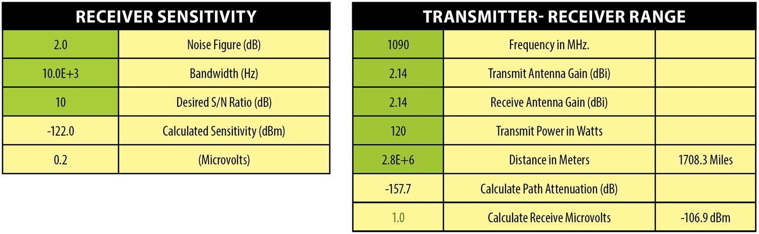
On the transmitter side, it seems that the satellite can be a bit over 1700 miles away (1708.3 to be exact) with a 120-watt transponder transmitter to provide a 1-microvolt signal to the satellite, or roughly five times more than we need for the system to work.

So here is my idea: A simple dipole has a “radiation pattern” that looks like a figure 8—sort of a big fat donut with a hole in the middle. It can radiate up and down simultaneously. The signal that goes to the ground station is also going up into space to “squirt the bird” at the same time. Two antennas are not required with this concept.
Is there some electronic reason that this will not work? No, we’ve been using dipoles for an awfully long time now (Google “Marconi 12 December 1901”), and we are pretty sure we know how they are going to work. However, there are a few tricks that we are going to have to play to get the antenna to work well up at a gigahertz (1090 MHz).
Will the Iridium system work this way? This I do not know, but this idea may well give us some ideas to question the designers of the system. And if so, we ought to be able to cut a lot of the expense out of the airborne electronics that now require two transponder outputs and the accompanying switching and power circuitry.

The accompanying drawings and photographs should be enough to give you a head start in making one of these little gems, but before we jump the gun, I hope that somebody will get a definitive answer from the Iridium system designers that a simultaneous signal to the satellite and the ground station will make the system work.
Next month: B.S., M.S., and Ph.D. (bull stuff, more of the same, piled higher and deeper). Until then…Stay tuned…


The dipole is one obvious answer to diversity as Jim points out. It is however a bi-polar solution to the tunnel focus of Nav Canada. They in fact “believed” 2 years ago that a bottom mount antenna “should” work with their Aireon final solution. They however missed the fact that RF propagation doesn’t work that way at 1 GHz. They could have looked at the 1970’s FAA papers on modelling of transponder antennae on various airframes and positions. The best reading of the numbers indicated that there would be a 20 to 30 dB loss. So starting with 125W on the bottom would effectively be 1.25W to 0.125W. Then of course there is the path loss of that 450 nm to the satellite. But, what if you simply move your monopole antenna to the top of the fuselage? Although the antenna isn’t ideal for Sat comms, it will work. But will it work for terrestrial ADS-B? Actually the antenna pattern is almost the same horizontally. This is what counts but don’t get too many obstructions in the way. The path loss is at least 6 dB better to the ground stations.
This is actually what I’ve been using on my Searey amphibian for the last 4 years.
Do I think that Aireon is the gold standard for ADS-B? Absolutely NOT. There are serious issues of 1090 saturation and the beamwidth of fruit from the 39 antennae in the Aireon satellite. Aireon is for AIRLINERS, and not too many of them. Consider also the comment of concentrating all that processing up 450 miles in the air where you can’t fix it. Can the security of this network be guaranteed? What’s the plan in a cyber attack of the GPS or Aireon networks? Again, Aireon is for airliners, but you had better have a back-up, airliners do, but we don’t.
The answer is supplemental terrestrial ADS-B with 1090 and 978.strategically placed in terminal airspace (B,C,D) and along low level routes. Gosh, Nav Canada already has VHF and navaids along those routes. What a thought for a balanced ADS-B approach?
Screw antennae diversity on EVERYONE. Network diversity is required by NavCanada. And don’t throw away those radars with primary backup and weather coverage. (most Wx channels have already been disabled due lack of spares.)
Spot on target.
Comments are closed.