Last month’s column showed off a nifty $20 transponder antenna. As I normally do to pique my students’ interest in the “real world,” I took the antenna in to show my college electronics class. One of the students asked if it would work inside a plastic luggage carrier on the back of a motorbike for his GPS.
Dunno, I said. Let me think about it. Rather than just think about it, I cobbled one up, and sure enough…Ah, but I’m getting ahead of myself.
GPS, the modern day miracle navigation system, has been as much of a paradigm shift in piloting as the VOR was back in the 1950s when it replaced the old AN range. Remember that? Four “on course” signals that were rooted in the bowels of the earth? Along comes the wunderkind VOR and you could have (gasp!) any one of the 360 degrees around the VOR station. But again, the VOR station was anchored to the roots of the planet.
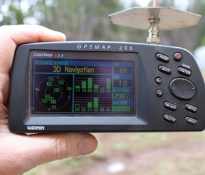
Performance with the ground plane antenna directly connected to the antenna port on the GPS receiver.
Enter the Satellite
Along comes GPS and all of a sudden there are no more roots. The 32 (24 operational plus eight spares) orbiting satellites (called the GPS constellation) pass overhead once every 12 hours, and at a given point in time, there are at least six and at most 12 satellites visible. The most probable number is nine satellites visible at once.
Each satellite spits out a pulse train at the exact same time. This pulse train consists of the accurate atomic clock inside the satellite’s time and where the satellite thinks it is relative to earth. Given that these pulses come from the satellite at the speed of light, it is relatively simple to calculate the distance from the GPS receiver to the individual satellite. Geometry tells us that we are somewhere on a sphere at a precise distance from the satellite. If we have two satellites in range, then we know we are at the intersection of these two soap bubbles. If you think about it, two soap bubbles that touch define a circle, so the GPS receiver is somewhere on that circle. When there are three satellites in range, they can only intersect at two points in space. One is on the surface of the earth and the other is somewhere in space. I think we know which one we keep, so that point is our precise point on the face of the earth.
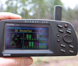
Performance with the factory rubber duckie. Note that signal strengths are greater, but fewer satellites are received.
Ah, grasshopper, but if you can “see” four satellites, you can derive altitude information from the pulse trains, and now we know in three dimensions exactly where we are North-South, East-West, and up-down).
Not to confuse the issue, but it is important to know that we are receiving GPS signals at 1575.42 MHz or just slightly above the transponder frequency of 1090 MHz. We already have a calculation for the transponder antenna, so it should be fairly simple to translate our results from last month to this simple little antenna.
Sure it is. Plug 1575.42 MHz into EZNEC, a computer-antenna modeling program, and it spits out that we need to make the little radiating rod 1.76 inches long instead of last month’s transponder antenna rod length of 2.54 inches. Another BNC connector, a hunk of copper tubing, a few square inches of aluminum for a ground plane, and away we go.
How Does It Work?
This actually worked better than I expected it would. Using our little ground plane “whip” antenna versus Garmin’s “rubber duckie” shows that the position accuracy is better, and it has more visible satellites. On the other hand, the satellite signals that the Garmin rubber duckie saw were stronger than what the homebrew whip recognized.

Mounting the antenna on the top of a 3-foot “antenna mast.”
Why? The reason is polarization. All radio waves transmitted have one of three polarizations. The two you are familiar with are vertical and horizontal. The com antenna sticking straight up from the fuselage is vertically polarized. The nav antenna (rabbit ears) on the vertical stabilizer is laid out horizontally and thus produces horizontal polarization.
The GPS signal coming from the satellite is the third form of polarization. This is called “circular” polarization, in which the signal doesn’t go up-down or side to side, but instead continuously rotates. As you might imagine, the signal can rotate clockwise (right-hand circular polarization) or counterclockwise (left-hand circular polarization). In the case of the GPS, we use right-hand circular polarization (RHCP). Any signal that doesn’t come direct from the satellite (like a signal bounced off of a building) will get its polarization changed from right to left and thus give us errors unless we design our antenna to only receive RHCP. That is what the Garmin does.
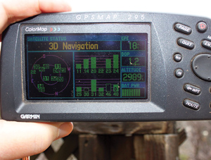
Note that with the antenna on a mast you get many more satellites and a stronger signal.
Our little whip antenna receives only half the signal power from the satellite because it is polarized vertically (if held vertical) or horizontally (if held horizontal). However, the increased efficiency of the ground plane configuration compares well with the store-bought rubber duckie as you can see from the photos.
It is also true that our little whip antenna can be moved some distance from the receiver into a more advantageous position, increasing the signal strength even more. Just putting it on a 3-foot “antenna mast” shows a navigable signal from 11 of the 12 visible satellites (the one it doesn’t see, No. 22, is just about to become invisible on the eastern horizon).
“But I don’t have room for a hunk of aluminum ground plane on my bike,” my student says. Not a problem. You can use two 3.75-inch lengths of copper tape, brass brazing rod or the like, and make them into an X or a +. Put the copper strips inside the luggage box on the bike, and drill a hole in the center of that X or + so that the rod antenna can stick up outside of the luggage box. If it were up to me, I’d put some sort of sturdy insulator around that rod so that if I got into a serious argument with another vehicle, the rod wouldn’t stab me in the process.
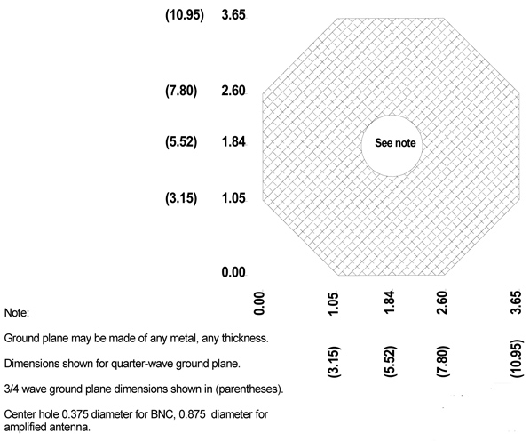
Dimensions for both a 1⁄4 and 3⁄4 wave ground plane.
One more thing and we’ll be done. If you have a fairly large store-bought amplified GPS antenna, you might want to consider a 3⁄4 wave instead of a 1⁄4 wave ground plane. It is a little known fact that ground planes may be made in any odd integer multiple (1, 3, 5, 7, etc.) of a quarter wave and will work just fine. The photo shows a commercially available (RST-8776) amplified GPS antenna that will let you put the antenna up to 15 feet away from the receiver using lightweight coax cable and still provide superior performance over the built-in or rubber-duckie antenna.
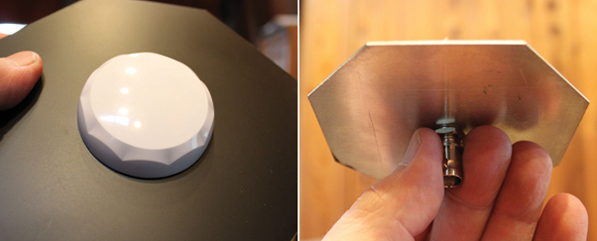
| Top of antenna mounted on ground plane. | Bottom of small whip on ground plane. |
I have received a few questions on ground planes for a com antenna inside a plastic or wood aircraft, so in a future article we might just touch on this and in passing talk about the whole com antenna structure.


