“…Now go cat, go…But don’t you…Step on my Blue Suede Shoes.” Elvis was singing this in 1957, and yes, I convinced my mom that I needed blue suede shoes to graduate 8th grade that year.
So, this is going to be another one of those multi-topic columns where I have three seemingly disconnected subjects that by themselves don’t rate a whole column, but with three of them we have a full article: GPS antennas, coaxial cable, and cable ties.
GPS Antennas
Let’s talk antennas in general for just a bit. Here’s the deal: Each and every radio has either an input or an output “impedance” depending on whether we are talking a receiver or a transmitter. A transmitter delivers maximum power into its designed load impedance. For example, take a transmitter designed to drive a 50-ohm load. That transmitter can’t tell whether that 50-ohm load is a simple resistor that is taking the transmitter’s power and converting it to heat or if it’s an antenna designed to look like a 50-ohm resistor but is actually radiating that power into the atmosphere. Reciprocally, an antenna designed to look like a 50-ohm load will convert all of the power it receives from a distant transmitter and deliver it to a receiver designed for a 50-ohm input impedance.
Now let’s talk about GPS antennas. For a reason that involves WW-II radar development, Popsicle sticks, British sharpshooters, plumbing, and squirrels, most all of the radios we put in airplanes are designed to work in a 50-ohm system. The input circuit of the GPS receiver, the antennas that drive them, and the coax that connects them are all designed with a 50-ohm “characteristic impedance.” The problem is that all of the GPS satellites are contained in the area above us from horizon to horizon in all directions. A second problem is that we can’t be sure whether the satellites’ antennas are vertical, horizontal, or some cattywampus angle in between.
Just as an aside, every radio in your airplane is designed in the 50-ohm paradigm. Woe to thee that wires your airplane with that “surplus” 72-ohm coax stuff and expects it to work properly. It probably will not.
Let’s be a little graphic about this. Take a tiny plastic airplane. Put it in the middle of a piece of paper. Cut a grapefruit in half and put half a grapefruit (skin side up) onto that little airplane with the airplane in the middle of the grapefruit. The GPS antenna on that airplane needs to see each and every little tiny spot on the skin of that grapefruit. Not only that, but if we tumble the grapefruit around, the antenna needs to follow that tumble while being electrically connected to that little tiny spot.
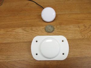
That’s a large order for any antenna, but fortunately our electronic bag of tricks contains an antenna that first saw the light of day in 1972. The “patch” antenna is simply a “large” sheet of copper bonded to the bottom side of a sheet of fiberglass, with a small patch of copper about 2 inches square pasted to the top of the fiberglass (plain old PC board material). By using dielectric insulators other than fiberglass, we can get that ground plane dielectric patch down in size to the point where the whole antenna can be put into a plastic bowl about 3 inches in diameter.
Here’s how it works: That sheet of copper on the bottom of the dielectric is the ground plane for the antenna, and the little postage-stamp-sized patch of copper on the top of the dielectric is the antenna element itself. But the magic is this: Remember the old “sled” marker beacon antennas—the bent “J” wire on the belly of the airplane? One end was grounded to the airframe, and the other end was a quarter wave away from the end. Through the magic of RF radio theory, that grounded end was (as you might expect) at zero ohms with respect to ground, and the far open end was almost at infinity ohms with respect to ground. Somewhere between zero ohms and infinity ohms, the number 50 ohms resides. The exercise was to tap the antenna at this magic 50-ohm spot and run the resultant marker beacon signal into the marker receiver.
How a patch antenna is made. Note that the patch antenna has its own ground plane and does not need to be mounted on a metal surface for a ground plane.
Same for the patch antenna. Zero ohms is in the middle of the patch, infinity ohms is at the edge of the patch, and “somewhere” in between is 50 ohms, which is where we attach the receiver coax. And, if we attach it off-center, one nice result is that the “polarization” is neither horizontal, nor vertical, but what we call “circular.” That means it doesn’t really matter to us how the satellite rotates; the signal to the patch antenna will be constant, and the circular polarization of the antenna follows the circular rotation of the satellite.
Now we address the final problem. The signal received by the aircraft GPS antenna is measured in nanovolts (a nanovolt is one thousandth of a microvolt). It’s a very tiny signal. Having a circularly polarized antenna doesn’t help as it cuts the signal in half at best. If we simply run a long cable to the GPS receiver, we’ve added some more loss in the cable. Not a good situation. Fortunately, we’ve got some really neat little (and I do mean little) microwave amplifiers that give us boosters right at that antenna (before the cable loss) with a gain of a thousand or so. Now we can deliver microvolts to the GPS receiver, which is where we want to be.
Then we put it into a plastic cup, run some BID glass around it, put a connector on it, and you have your GPS antenna.
Coaxial Cable
To connect the antenna to a GPS receiver, we need to run cable. Not just any cable, but coaxial cable. Coaxial means that we run two wires, one inside of the other. One is called the center conductor, which is covered by an insulator, and one is the braid or shield over the insulator.
How about some coaxial cable history? Just before WW-II, the British invented radar. Send a huge pulse of RF energy out, and see what bounces back off of an aluminum airplane. Given time out and time back, we can estimate the distance. The problem was the huge pulses of RF energy. The radar was at the bottom of the hill (to keep it from being bombed or strafed), the antenna was at the top of the hill, and the only thing at the time we had to connect the two was what is commonly called a ladder lead—two wires separated by small Popsicle sticks going from the radar to the antenna. Squirrels just loved to run up and down the ladder lead until one of them stretched across the ladder wires…and fried the squirrel. Unfortunately, the radar tube didn’t like the impedance of fried squirrel and fried itself at the same time.
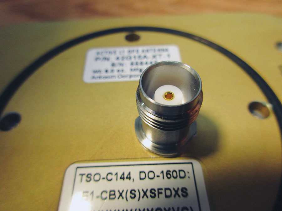
The TNC connector coming out the backside of the large antenna. The small antenna has 15 feet of coax preinstalled. TNC (as opposed to BNC) seems to be the industry standard for GPS antennas. The T and the B stand for “threaded” and “bayonet” respectively.
So the British had sharpshooters pick off the squirrels from the ladder line. The problem was that the radar needed to work in the dark as well, and you couldn’t see the squirrels in the dark. So one engineer said there was a secondary form of transmission line, one that involved a center conductor carrying the energy and an outer conductor carrying the “return.” Sort of like the black wire on your home being the “hot” wire and the white wire being the return.
A lot of math and a lot of experimentation with this newfangled “coaxial” transmission line took place in a very short time span (1938-1941), and we found that the ratio of the center conductor diameter to outer conductor (“shield”) diameter had a characteristic impedance, and we could have nearly any impedance we wanted by varying this ratio. We also found that a 72-ohm ratio was best for minimum loss, and a 32-ohm ratio was best for maximum power handling.
The British decided to refit their radar with this “coax” cable, but it needed to handle dozens of kilowatts of peak power, which meant rather large coax. Since copper is the second-best conductor of electricity (silver is marginally better), they decided to use what was commercially available on the market to make their large coax. They found two common sizes of British water pipe copper to use as their outer and inner conductors. When they did the math, they found that these two common diameters were nearly halfway between best power (32 ohms) and best loss (72 ohms), and wound up being 50 ohms as the compromise between these two. The world has been dancing to the RF world of 50 ohms for the last 80 years, thanks to a British plumbing standard.
Sometime in the next few months we’ll revisit coax cable and get a little more scientific.
Cable Ties
Here’s number 3 real quick. I hate nylon tie wraps for a few reasons. One, they rapidly deteriorate over time. Two, if you don’t cut them off perfectly, they are little sharp-edge skin rippers. Three, they are moderately expensive.
Here is a really inexpensive and very effective method that has been around for nearly 100 years: waxed twine. Yep, good old polyester twine that comes pre-waxed at about ten ties for a penny. But there are two tricks, and here they are:
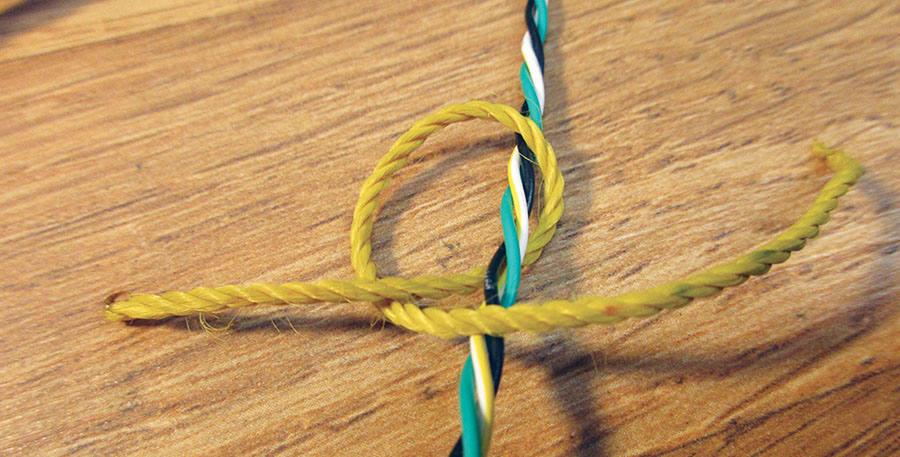
• The twine is tied very tight with a single loop to a square knot, but be careful. It is quite possible to cut a wire in the bundle with the mechanical advantage of that loop and Gus, the gorilla, tying the knot.
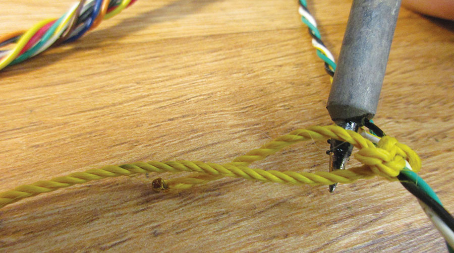
• The twine is end-sealed by cutting it off with a hot tool like a soldering iron or gun.
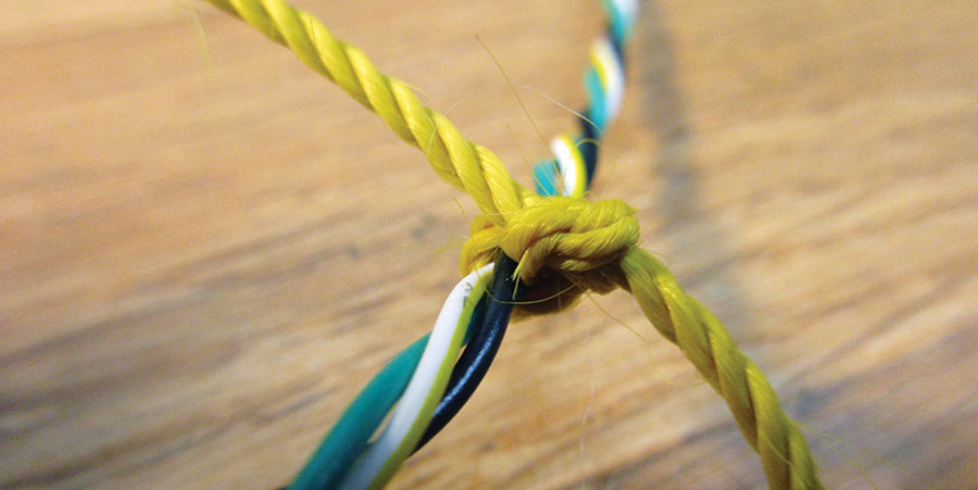
A square knot is tied after pulling the twine tight. (Careful now, that loop-around doubles the force you can apply.)
The end result is a very strong, very small tie that is nearly impossible to come loose due to the melted ends. There’s about ten wraps for a penny’s worth of twine.
Durable? I’ve got some WW-II bits and pieces around I keep for history’s sake, and the nylon twine ties are still as good today as they were 75 years ago. No deterioration whatsoever. Just make sure the twine you buy ($16 for 187 yards on Amazon) is waxed.
As always, see you next month, and stay tuned…











Mr Weir, you’re an excellent teacher. you make one “see” the story, and for a visual thinker like me, that’s awesome.