Over the next couple of months, these columns will be a compendium of little ideas that Ive been asked about over the years, simple, but that will give you some brief explanations of how you might rig your homebuilt electrics.
First, some thoughts about pilot lights. Im fascinated with the term, as those little lights that show the equipment is on have nothing to do with pilots or leading the way, or anything else having to do with the real meaning of pilot. They have been called pilot lights since the beginning of radio (the 1920s for sure), and we will honor history by continuing to call them that.
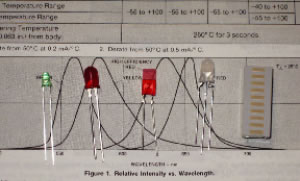
A variety of LEDs. From left to right, a T1 green, a T1 3/4 red, a rectangular red and a two-color (note the three leads)
By All Indications
In todays world, the LED is king when we talk about indicator lights; they are two bits apiece and have a theoretically infinite lifetime. I wish I had a dollar for every time Ive been asked to supply a 12-volt LED. There is no such thing. Red LEDs operate somewhere in the 1.9-volt range, yellow and green around 2.1 volts, and blue and white around 3.5 volts. So how do I get them to operate from the aircraft electrical system? Relatively simple: Use a dropping resistor.
Understand that LEDs are current-driven devices, not voltage-driven lamps like an incandescent bulb. How much current depends on how long you want the bulb to last. Most small pilot light LEDs are rated at between 20 to 30 milliamperes for long life (mA is a thousandth of an ampere), so let’s split the difference and do the calculation for a 25 mA lamp.
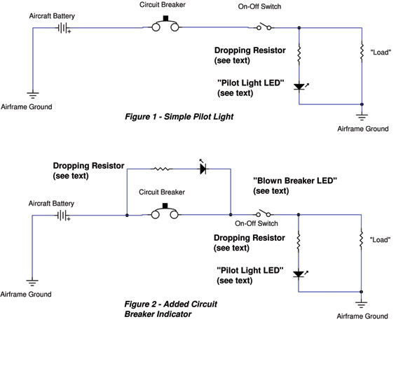
Ohm again, Ohm again, jiggity jog. Yup. Old Man Ohm to the rescue. Lets see now, for a 12-volt system, the nominal running voltage is 13.6 volts or thereabouts (See Figure 1). To operate a red LED (1.9 volts) at 25 mA from a 13.6-volt system, we note that the drop across the current limiting resistor is (13.6 – 1.9) 11.7 volts. To have a resistor drop 11.7 volts while passing 25 mA of current, Ohm tells us that R = E/I = 11.7/25 e – 3 = 468Ω (470Ω). The precise value is 468 ohms, but 470 is the nearest standard (off the shelf) value. Oh, you have a 24-volt ship (25.3 nominal bus voltage)? No problem. Use the same equation, only substitute 25.3 volts for 13.6 volts, and you find that your dropping resistor should be 1012 ohms, or a standard value of 1000 ohms (1.0 Kohms).
What about a blown fuse/breaker warning? OK, heres the deal. You have a load on that fuse/breaker. No matter what the load is, you can represent it by a resistor. It has voltage across it and current flowing through it; therefore, it can be thought of as a simple resistor (see Figure 2). How about that, you have a brand new whizbang kilo$$ radio, and I call it a penny resistor. For our purposes, it is just that.
Heres what happens. Under normal circumstances, there is an equal amount of voltage on either side of the breaker, and that means a dead short across the resistor-LED combination. However, when the breaker opens up, you get 12 volts on the battery bus side of the breaker, and the LED finds ground through the on-off switch and the load resistor.
Some practical thoughts. Me? I make the pilot light green and the blown breaker light red. You have red, orange, yellow, green, blue, and white LEDs to play with, so make the colors mean something to you when they light up. Green is good, red is bad, white (be careful, those suckers are bright) might be a landing light or something, yellow is caution and so forth.
How about size? LEDs come in a variety of shapes and sizes. The most popular are the dome-top T1 (3mm) and T1 3/4 (5mm). However, you can buy LEDs that are square, triangular, super-tiny surface mount (and some day Im going to get some Plexiglas and make a few of those expensive edge-lit instrument bezels from surface-mount LEDs), rectangular and a few other oddball shapes.
Mount Up
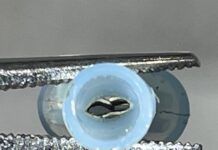
The cheapest way to fasten an LED to your instrument panel is with a rubber grommet. A standard grommet with a center hole of 3⁄16 inch fits a T1 bulb just fine, and a grommet with a 3⁄16-inch center hole fits the T1 3/4. (These are the Keystone 733 and 736, respectively, but a dozen vendors make an identical part.) Drill a mounting hole in the panel, insert the grommet, pop the LED into the grommet and bingo, a panel light.
There are other ways of mounting LEDs. One of the best is what is called a Fresnel lens that adds another two bits to the price of the lamp assembly. See the Mouser series that starts with 593-1700 for the idea. Here a cylinder of colored plastic is molded with internal retaining tabs for the LED. You drill a hole of the proper diameter, pop the LED into the lens, and bingo, you are using the entire output of the LED focused out the front of the instrument panel.
There are dozens more. If you intend to play this game for real, Id suggest that you get a paper copy of the Mouser catalog and study the LED lamp section. In the current catalog, thats pages 95 through 150, 55 pages of every LED imaginable and some unimaginable ones!
Wired
Save the best for last. Wiring the little rascals. It isn’t all that difficult. I like to use a very thin wire between the power source and lamp and another thin wire between the lamp and ground. Thin? My choice is Mil-W-76C PVC #24 stranded wire for a few reasons. One, it is lightweight and we all know that a pound saved is a pint of fuel more. Two, it is readily available in every color of the rainbow. An investment in a dozen 100-foot spools of different colors will really help in the years ahead when you start troubleshooting your decades-old homebuilt. Or just get two colors (white and black) and read next months column when we go into wire marking and power strips. For aircraft stuff, it is fairly inexpensive at $30 for a 100-foot spool (half that price if you buy a 1000-foot spool and share it with your chapter friends). The last thing I like is that the fusing current of #24 wire is about 29 amps (www.rstengineering.com, Jims Engineering Page, Wire Tables), and even a moosey 20-amp breaker will break and wont fuse the wire if it accidentally shorts to ground.
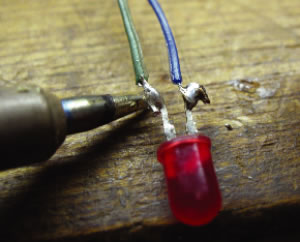
Soldering the wires to the LED.
Now for the method. First, cut the LED leads to about half an inch long. Then bend outside hooks onto the leads. Cut both leads of the dropping resistor to half an inch and bend a hook into each end. (On the blown-breaker setup, I put the dropping resistor directly at the breaker inside of a crimp terminal. That way if the LED anode wire gets accidentally shorted to ground, all you get is about 25 mA of current, hardly enough to cause any smoke or other character building events.) Hook one resistor lead into the anode lead hook of the LED (see the picture in the Mouser catalog for your particular diode to tell how to identify the anode and the cathode). Squeeze both hooks together and then solder the hooks together.
Use a readily identifiable color for the cathode wire, strip one end half an inch, tin the wire with solder, bend a hook in the wire, and connect the wire to the cathode hook, squeeze, and solder. Similarly, connect an identifiable color to the free end of the dropping resistor, squeeze, and solder. Then cut two pieces of 3⁄16-inch shrink sleeving that are long enough to completely cover from the bottom of the LED over the exposed hooks of LED and resistor, install, and shrink. (Hint: A hair dryer makes a remarkably good substitute for a real heat gun.) Then take a piece of -inch sleeving and shrink over the whole assembly from the bottom of the LED to the end of the small shrink sleeving.
Thats about it for the LEDs, folks. There will be more little bitty hints for wire marking and power strips next month.


