In last months column, I promised to give you a little more information on voltage regulators. That could be a complete semesters worth of graduate school work, so I am only going to touch on the highlights.
Why do we need a regulated voltage? There are several reasons, but the main one is that the battery system in light aircraft may vary more than 2 volts from no-charge to full-charge on the battery. That just isn’t going to cut it for some integrated circuit work or for some delicate low-noise work. In addition, if you play it right, that noisy, spiky battery/alternator source can provide a nice, clean, quiet voltage to power other items.
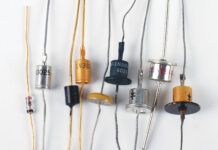
In the late 1950s, Clarence Zener (Westinghouse in conjunction with Bell Labs) invented a silicon diode that acted just like a normal diode when biased in the forward direction, but had an interesting characteristic when biased in the reverse direction. This zener diode would not conduct any current at all in the reverse direction until a critical voltage level was reached (the zenering voltage), and then it would conduct a lot of current. This zenering voltage could quite easily be controlled during the manufacture of the diode to produce nearly any zener diode voltage that you desired. Zener diodes are available in voltages from less than 2 volts to several hundred volts and are fairly cheap (less than a nickel in moderate quantities).
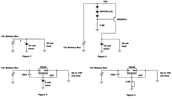
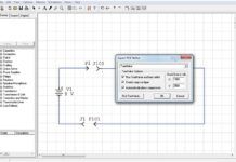
Zener diodes are the first level of regulation. If the circuit they’re used with has a relatively constant current draw, then the zener all by itself is more than enough (See Figure 1). The only question left is how to calculate the value of that current-limiting resistor, so here we go. We know that the load is going to draw 20 mA from the 10-volt supply (thats a given). Most small zeners do pretty well with 10 mA of current flowing through them. The total current draw is then 30 mA. The battery supply is 12 volts and the zener is 10 volts, so there will be 2 volts across the resistor in question. Ohm (that pesky devil again) says that R = E / I = 2 / 0.03 or 67 ohms. However, you cant buy 67-ohm resistors; the closest standard value is 68 ohms.
Now old man Watt raises his head. With 10 mA flowing through a 10-volt zener diode, the diode is dissipating P = E x I, which is 10 volts times 10 mA, or 100 milliwatts (0.1 watt). However, this is based on a 12-volt battery. We know that in undercharging conditions that battery can get up to 14.4 volts, so now the current in the 68-ohm resistor has risen to I = E / R, which is (14.4 – 10) / 68 or 64 mA. The load is going to use only 20 mA of that, so we are left with 44 mA to run through the zener. This, then, in accordance with Watts Law, means that the diode will have to dissipate 440 mW of power, and most small zeners are heat-limited to 400 mW of power. Not only that, but running a small diode like this near its power limit means that the chip inside the zener case will get hot, which causes further errors in the zener voltage, and so on. Not a good deal.
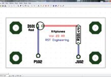
Well, Ohm got us into this mess, and Ohm will get us out. All it will cost is about 10 cents worth of parts: three diodes, two resistors and one transistor (See Figure 2). The circuit that replaces the 68-ohm resistor is called a constant-current configuration. Without going too much into the mumbo-jumbo of the design, the three diodes present a fairly constant 2.1-volt drop from the battery bus when fed from the battery supply and then through the 1.0KΩ resistor to ground. The transistor loses 0.7 volts of that between base and emitter, leaving 1.4 volts on the emitter relative to the base. Ohm tells us that if we want 10 mA to flow into the emitter (and thus through to the collector, the resistor from battery bus to emitter needs to be R = E / I = 1.4 / 10 mA = 140Ω. We cant buy 140-ohm resistors; 150 ohms is the closest standard value. This will easily give us a constant 10 mA into the zener from 12 to 15 volts.
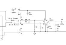
That seems like a lot of folderol for a simple source to supply a small amount of current to a load. Surely there has to be an easier way, and there is. Jack Kilby and Robert Noyce (Texas Instruments and Fairchild Semiconductors, respectively) in 1958 came up with a newfangled device called an integrated circuit that could take all the resistors and all the transistors and most of the capacitors of a complex circuit and etch them onto a single crystal of silicon about a tenth the size of a grain of salt. One of these devices happens to be a voltage regulator, with all the stuff we hassled about with our discrete design and a hundred times more in the chip design (See Equivalent Circuit).
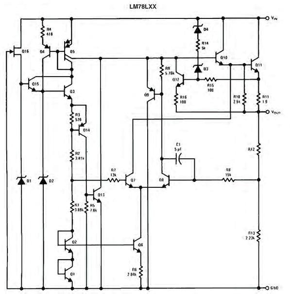
Equivalent Circuit.
What will this 78L05 device do for us? In the first place, it will dissipate about 500 mW. In the second place, it is short-circuit proof. In the third place, if we try to draw too much current, it will shut itself down. In the fourth place, if it gets too hot, it will shut itself down. All of this for about the same price as the parts we used in our simple circuit.
What are the downsides of using this IC chip? The device comes in only three flavors: 5 volts, 12 volts and 15 volts output. We’ll have to trick it to make it give us 10 volts. Not a big deal. It does need a couple of discrete parts, one capacitor and one resistor.
The first trick (See Figure 3) is to add another 5 volts into the ground, or common lead, to offset the 5-volt regulator with another 5 volts from the 5-volt zener diode. Note that this can be done with any voltage diode you wish to give oddball voltages such as adding 4 volts to run your 9-volt transistor radio or two plain diodes in series to give you about 6 volts to run your satellite radio.
The second trick (See Figure 4) is to give you a continuously variable output all the way from 5 volts to 10 volts and anywhere in between. Simply rotating the potentiometer will let you set the voltage where you want it.
The 100 nanofarad (0.1 microfarad) capacitor is important. With any kind of lead length at all between the battery and the input of this little gem, the regulator will oscillate without this capacitor. The reason is rather obscure (a plain old wire is not only a resistor, but also an inductor) but take it from me, you really want this capacitor in there.
That about does it for relatively low-power voltage regulators. Ill come back in a few months with some regulators that will give you some real power output (amps, not milliamps), but Id also like to get Back Yard II done and in place. See you next month right here.


