 It has been a hectic couple of months here at Humberd Farms in Tennessee, which helps explain the extra month’s gap in this series. As I write this, we are getting ready to harvest corn silage. Between the harvest and the cattle, I’m expecting we’ll continue to be very busy for the next few weeks. Add another week working the Oshkosh AirVenture show—and all the other priorities in life—to the mix and the time to work on the 750SDX has been limited. Even so, there has definitely been some progress since last time.
As discussed in the last article, the ULPower 520T engine was delivered and I have been putting a lot of time into planning my custom engine mount. The good news is that I was able to find time to put this process into motion. And quite a process it has been!
Building a Custom Engine Mount
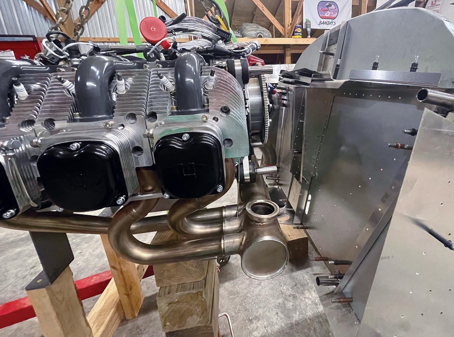
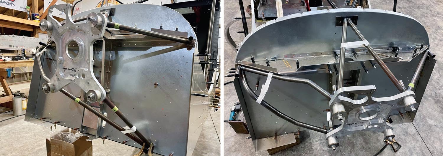
With that beautiful engine hanging on a hoist for a few weeks, I was able to really study how to tighten things up in the engine compartment and bring the engine position back 5.5 inches from the commercially available engine mounts. Using lasers, strings and plumb bobs, I got the engine precisely—and very carefully—braced in the correct position for the downward and right offsets to the firewall and began building the custom chrome-moly tubular engine mount.
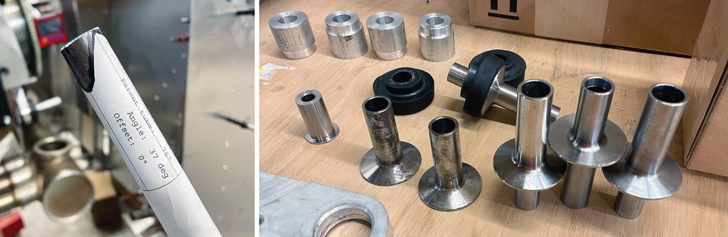
Acquiring the right parts started with engine mount pins from ULPower. There are two different types of pins on the available engine mounts: the firewall pins and the engine pins. The firewall pins are machined differently and are quite a bit heavier. I opted to do a little extra machining and use engine pins all the way around. Once machined, they are lighter and allow mounting to the firewall with shorter (lighter) mounting bolts, which seems like a win-win. While at the machine shop, I also had some aluminum bushings made so that I could use an engine backplate as a jig for keeping the engine mount aligned properly while I TIG welded the chrome-moly tubes.
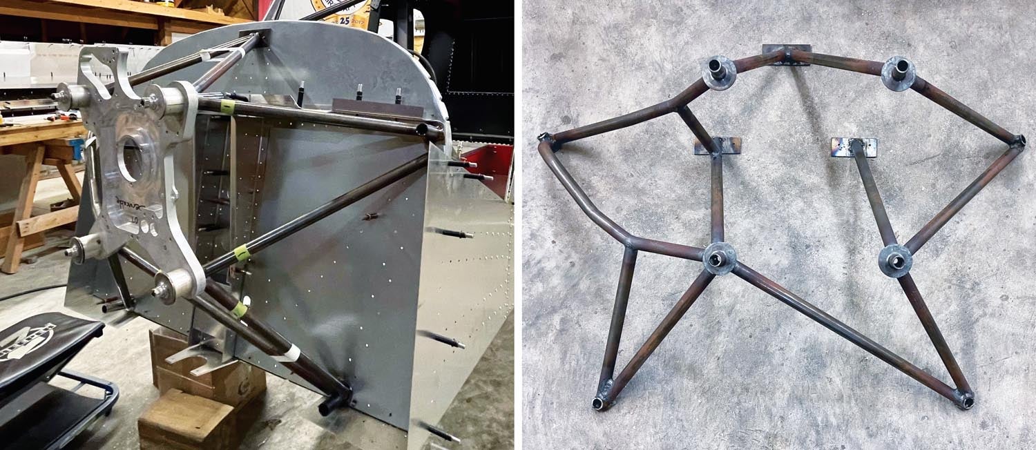
With all these parts and several feet of 3/4-inch by 0.049-inch chrome-moly tubing in hand, I was able to start cutting and putting all these pieces in place to mock up a completely new engine mount.
Making the 3/4-inch tubes fit nicely as I double-coped both ends of each tube and mocked up the mount has been quite an interesting learning curve. To help with coping the tubing, I found that metalgeek.com has an online coping tool, which allows you to plug in parameters and then gives you a file that can be printed, cut out and taped around the tube. I found this gave me an easy way to mark the tubing for precise cutting with a good cutoff wheel and belt sander.
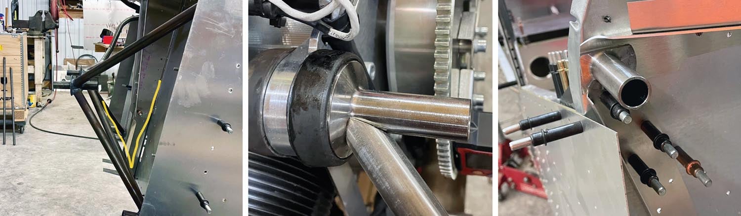
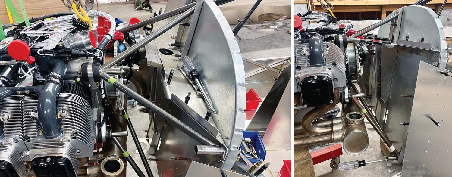
The first tubes were relatively easy, but as I moved toward fitting the tubes around the turbo, the entire project became quite a bit more challenging. It required tubing with bends and extra bracing at the center of the bends to maintain strength. Using bent tubes is never structurally as good as keeping tubes straight. A curved tube is basically already pre-bent and, when under stress, is more likely to continue bending than a straight tube.
While it was fitting like a glove at this point, I was concerned about the angles of the bottom tubes. If the angle coming from the firewall gets too shallow, it is more prone to collapse or fold due to the stress of the engine weight being bounced around while “off-roading.” To mitigate this, I opted to add additional tubes and mount points to the firewall, making it a seven-point attachment instead of the standard five-point attachment that is most common on the firewall of these STOL airplanes. The extra two attachment points are near the center of the firewall where there is already quite a bit of built-up bracing for the nose gear strut. I will also be adding additional bracing on the rear of the firewall at these points, which will be covered in a later article.
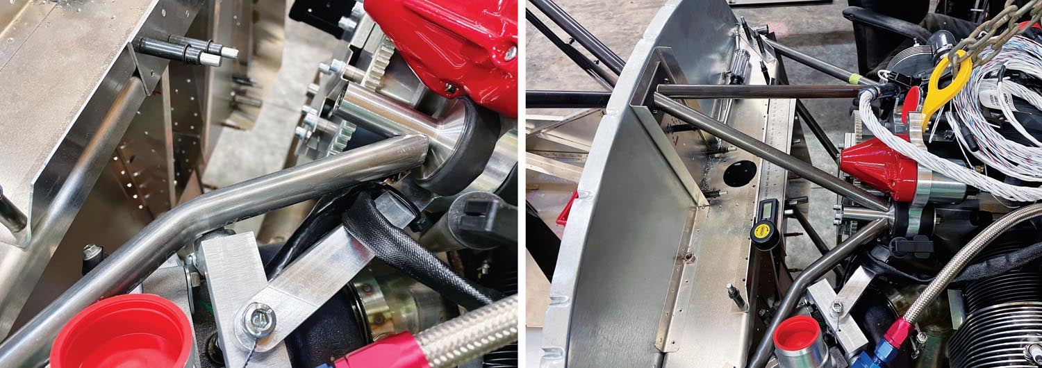
With most of the tubes cut and fitting very nicely, the last few began to show how much of a puzzle it can be to fit a tube that is double-coped on both ends into a nearly unmovable structure. To compensate, there was a lot of bolting/unbolting and Clecoing various parts of the engine mount pieces to allow those last few tubes to be trimmed and installed for a precise fit.
A precise fit is particularly important for welding chrome-moly tubing because the closer the tubes align, the less filler they will require while TIG welding. This will ultimately make a stronger structure than loose-fitting tubes that need extra filler material. Although it took a lot of time to make everything fit and work for my expectations, I eventually had the engine mount fitted, mocked up and ready to weld together.
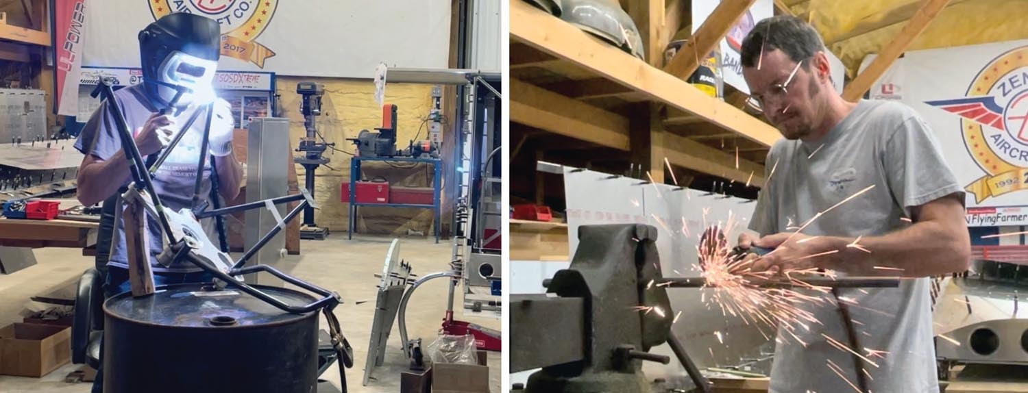
This presented a unique challenge in itself because the entire assembly needed to be tack welded together while mounted to both the firewall and the ULPower engine, all while still hanging in precisely the correct position on the engine hoist. With everything being so tight-fitting, there wasn’t much room to reach the tubes, control the TIG torch and also have the filler rod ready to reach the same spot at the perfect time for a good spot weld. Nevertheless, I did manage to get enough spot welds in place to hold the custom structure securely enough to remove the engine.
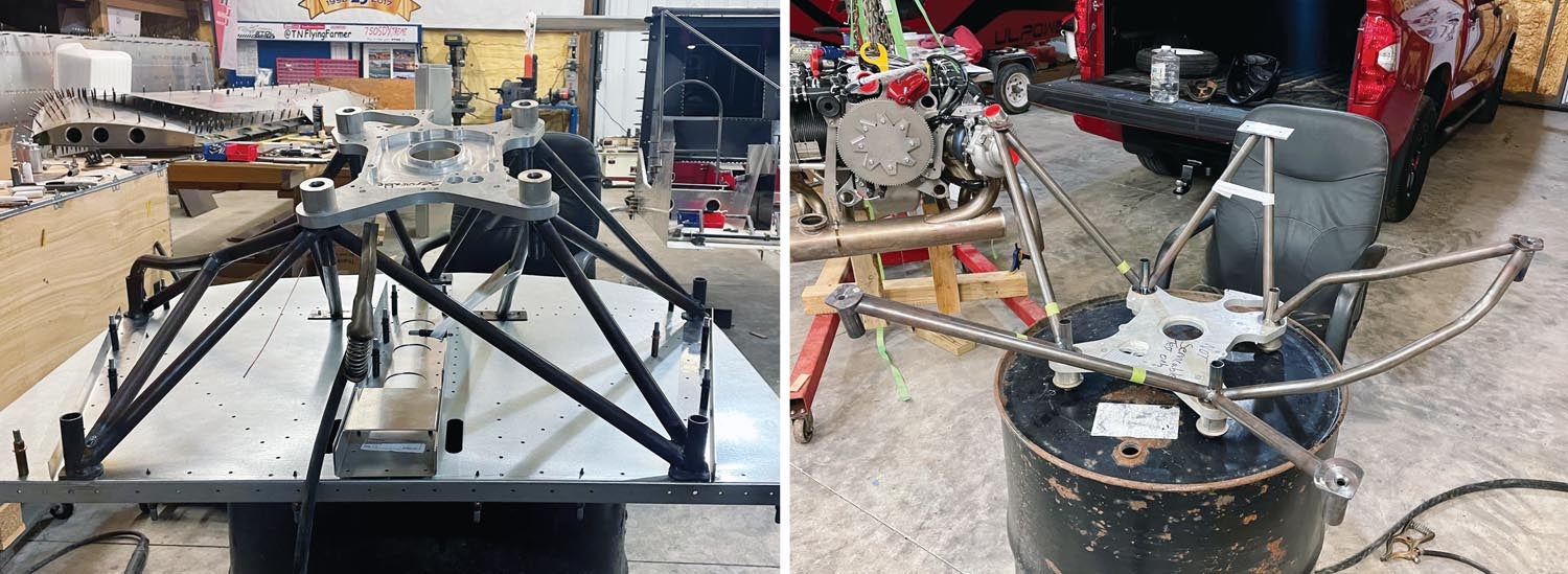
Once that was done, I moved on to installing the machined bushings and the bare engine backplate to the front of the mocked-up mount. This freed up a lot of room to maneuver the TIG torch and begin the final welding on the new engine mount, all while it was still mounted to the airframe and firewall. With all the angles and extra tubes, there were still several spots that were inaccessible for the final welding. As a result, I welded as much as possible, then removed the firewall from the airframe and used the top of an old 55-gallon metal drum as a farm shop welding table. Turning the whole firewall, engine mount and engine backplate assembly in all kinds of positions allowed me to weld almost all the rest of the custom mount. A couple of places required the removal of the backplate and then the firewall to get the last hard-to-reach spots. This process also gave me a new respect for professional TIG welders who do true freehand welding (standing and not having anything to lean your arms on while welding makes things a little more tricky).
Having done all of this, I will continue to tell everyone: If there is a commercially available engine mount, just buy it, bolt it all together and don’t go through what I did to build one. That said, there was a nice feeling of accomplishment when all the hours spent designing, cutting, fitting and welding up a completely new engine mount on my own worked out as planned.
More To Do
Even though it seems complete, there is still a lot of cutting, trimming and smoothing the edges on the tubing at all the mount pins yet to do. This helps reduce the weight even more and really improves the overall appearance of the finished product. All in all, I am happy to report that the complete short-coupled engine mount, even with the extra bracing and attach points, weighs less than the commercially available mount. This is due simply to all of the chrome-moly tubes being shorter.
The last steps yet to be done for the new engine mount include cleaning up those edges and then painting, so it will have a truly finished look.
Completion Goals
Just a few days after welding up most of the engine mount, I loaded up and headed to EAA’s AirVenture to work in the Zenith Aircraft booth. It is always great to see and talk to so many pilots, builders and friends at these events. With that being said, I am also now spending a lot more time in Tennessee.
As I get closer to completing the 750SDX, my goal is to demonstrate it and make it a showcase at several events in 2024. There is a lot to do in order to make that happen with this unique STOL airplane, but I am working out the schedule for the next portions of the build and it’s looking possible. Some of the things left on the agenda include more work with the forward fuselage, along with finishing the cabin frame and firewall construction, so I can paint all the rest of the chrome-moly components and prepare them for final assembly. There is quite a bit of work left to go in those areas, however, and if there is any downtime during this stage of the build, I still have plenty of other things to think about and other areas to work on.
Next in Line
Among the areas next in line for my building focus are a couple of interesting components that will be different from the standard Zenith kit. First, I have high hopes for getting this project off the temporary caster wheels as soon as possible, so the gear, wheels, brakes and tires will be an upcoming priority. One of the obvious changes from the normal kit will be the Beringer brakes and wheels that I will be using on this 750SDX. I always loved the looks of the Beringer system.
I plan to stick with the standard main tires—27.5-inch smooth tundra tires—that come with the Zenith 750 SD kit. These tires are a slightly bigger version of the 22-inch tires that I have been using on my Super701. They are probably the lightest available option for decent bush tires, should be big enough for most of the places I want to go with this airplane and even seem to hold up really well to pavement abuse.
The other thing that I currently have in the works is a custom/prototype nose strut with a full suspension system. I am really excited about this modification! I believe it could create a good solution for having a true rebound damping system and a better spring rate for utilizing Zenith planes away from pavement.

suspension system I’m trying. More to come on that in a future story.
The prototype strut is in hand and mockups are currently underway with hopes of making this improvement an easy modification using the current nose gear mount brackets. Of course, weight is also a major concern when working through all these modifications, so I am happy to report that this new nose gear suspension strut is very robust, but also adds full suspension without any weight gain! Lots more details coming soon!
Videos of Humberd’s builds—and some of the fun that can be had with flying a STOL airplane—can be found at www.youtube.com/@TNFlyingFarmer.
Photos: Jon Humberd.
![Coming in for a landing at Humberd’s Farm [All Images Credited to Jon Humberd]](https://www.kitplanes.com/wp-content/uploads/2026/07/9-1.jpg?w=218&h=150&crop=1 "Overcoming Setbacks on the Zenith 750SD Xtreme")
![[Credit: Zenith Aircraft Company]](https://www.kitplanes.com/wp-content/uploads/2026/06/31142685469.jpg?w=218&h=150&crop=1 "Zenith Throws Open Its Doors for “Fly-In to Summer”")
![Members of the North Idaho High School Aerospace Program gathered at KSZT [Credit: North Idaho High School Aerospace Program]](https://www.kitplanes.com/wp-content/uploads/2026/02/IMG_3499.jpg?w=218&h=150&crop=1 "North Idaho High School Student ACES Fly the Aircraft They Built")


