 Time for the instrument panel? You have dreamed of that panel every day since you started building. Now it’s time to turn that piece of aluminum into a finished panel. There are so many options. One option is to farm out the entire project. SteinAir produces works of art. Just give them a list of what you want, and they’ll send you a fully operational panel worthy of display in an art museum. However, you want to grow your own. This is Experimental aviation after all, and that’s why we do this.
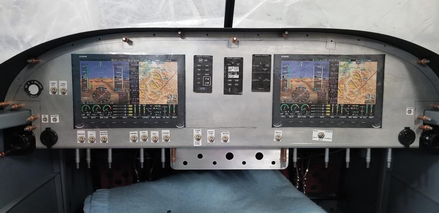
You’ve done the planning and at least have a mockup. What? No mockup? No worries. Download the specs and some photos for all your fantasy components. Download any CAD files as well. Save those for later. Download photos of switches, jacks, breakers, etc. Print the photos exactly to the dimensions in the specs. Have them laminated. Cut them to exact dimensions. Use double-sided tape to place them on the panel and start making airplane noises. Yes, it sounds silly, but you will live behind that panel. Pretend as if it’s real. Move stuff around until you are happier than a cat in a fish market.
Next, you’ll need holes. That means measuring, cutting, drilling, etc. It takes quite a bit of time. OK, now that the panel is cut, here come some more decisions. How should it be finished? Paint, vinyl, hydro dip or powder coat? What about all those labels? Rub-on, peel-and-stick, water transfer? Oh bother! So many choices.
How about a vinyl skin with all the labels printed? Just apply it and you’re done. What’s the cool part? The vinyl can also be printed, applied and used as a sacrificial cutting template. Simply have it printed on white vinyl, apply it to the metal panel and hack away! And changes? That’s a simple edit to the artwork and a reprint of the skin.
The industry is pretty tight-lipped. It took quite a bit of experimentation, visits to printers and some creativity to discover the process, but the final product is worth considering. I am a firm believer in sharing knowledge. There are a couple of caveats. One is the choices for printing and vinyl are somewhat limited. Most printers only print color on white vinyl. It’s called CMYK. More on this later. Usually, they use 3M 180MC vinyl. It comes in quite a few colors including a very rich black, but no carbon fiber. However, if you talk really sweet, they might try printing on some carbon fiber vinyl if you provide it. I purchased a 5×6-foot section of 3M 2080 Black Carbon Fiber Vinyl Wrap #CFS12. It turned out pretty nice. Let’s get started.
Precision Artwork
In order to print a sacrificial skin, then apply a finished skin, you need precision. The printer can only print the art you produce. Just like software, it’s garbage in, garbage out. You are the artist—yet another skill to add to your repertoire. In order to place the skin on a panel, it has to line up to the holes perfectly. So how do you get that level of precision?
Easy. If you’re building an RV, Van’s Aircraft has CAD drawings of the panels for most models available for download. Files are supplied in DWG, DXF or IGES format. If your project is not from Van’s, check with the manufacturer. They may have similar files available.
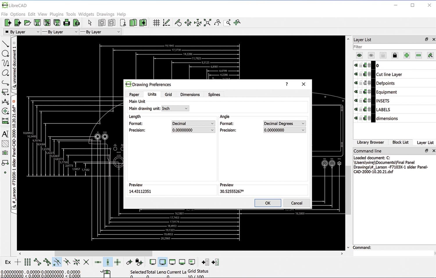
Download the drawing for your panel. Download a CAD program if you don’t already have one. If you have AutoCAD, great. I can’t afford it. I’m cheap and really like open-source software. Try LibreCAD 2D CAD software. It’s free and very similar in function to AutoCAD. If you love an open-source program, consider donating.
Notice that Van’s has placed the panel’s prepunched holes on the drawing. Eureka! You now have precision alignment points. The prepunched panels are cut from that drawing, so your panel screw holes should perfectly match the drawing. Save the file for now.
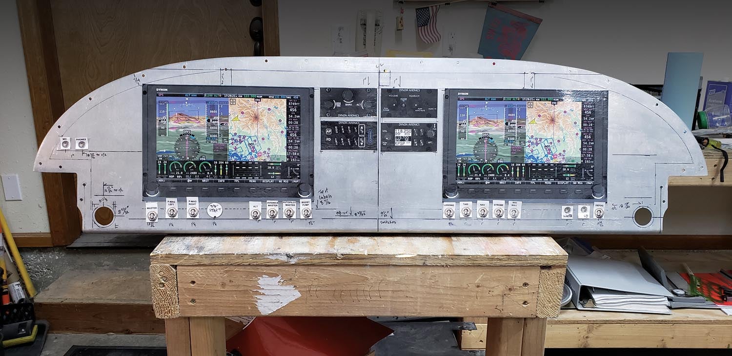
Draw a centerline top to bottom on the mockup panel and pick two screw holes (one either side) to draw a line across the panel. Check behind the panel for structure and mark the panel. You don’t want to find out when it’s time to slide in that huge 4K HDTV screen that it hits support structure behind the panel. Take location measurements of every device, switch, etc., on your mockup using these lines as alignment reference points. Since they all reference the Van’s screw holes, you can duplicate all the measurements quite easily in CAD.
You’ll need a few settings before proceeding with lines and circles. Since every CAD program is different, I will discuss what needs to be done and hope you can figure it out on your CAD software.
First, open the panel drawing and delete any extraneous text. You don’t need it. Save the new file as a DXF (drawing interchange/exchange format). A DWG (drawing) file is an AutoCAD proprietary format. If you’re using AutoCAD, feel free to use DWG.
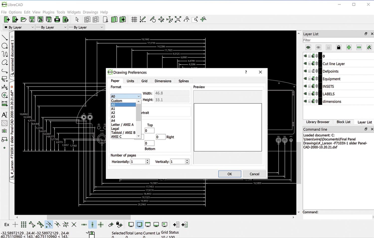
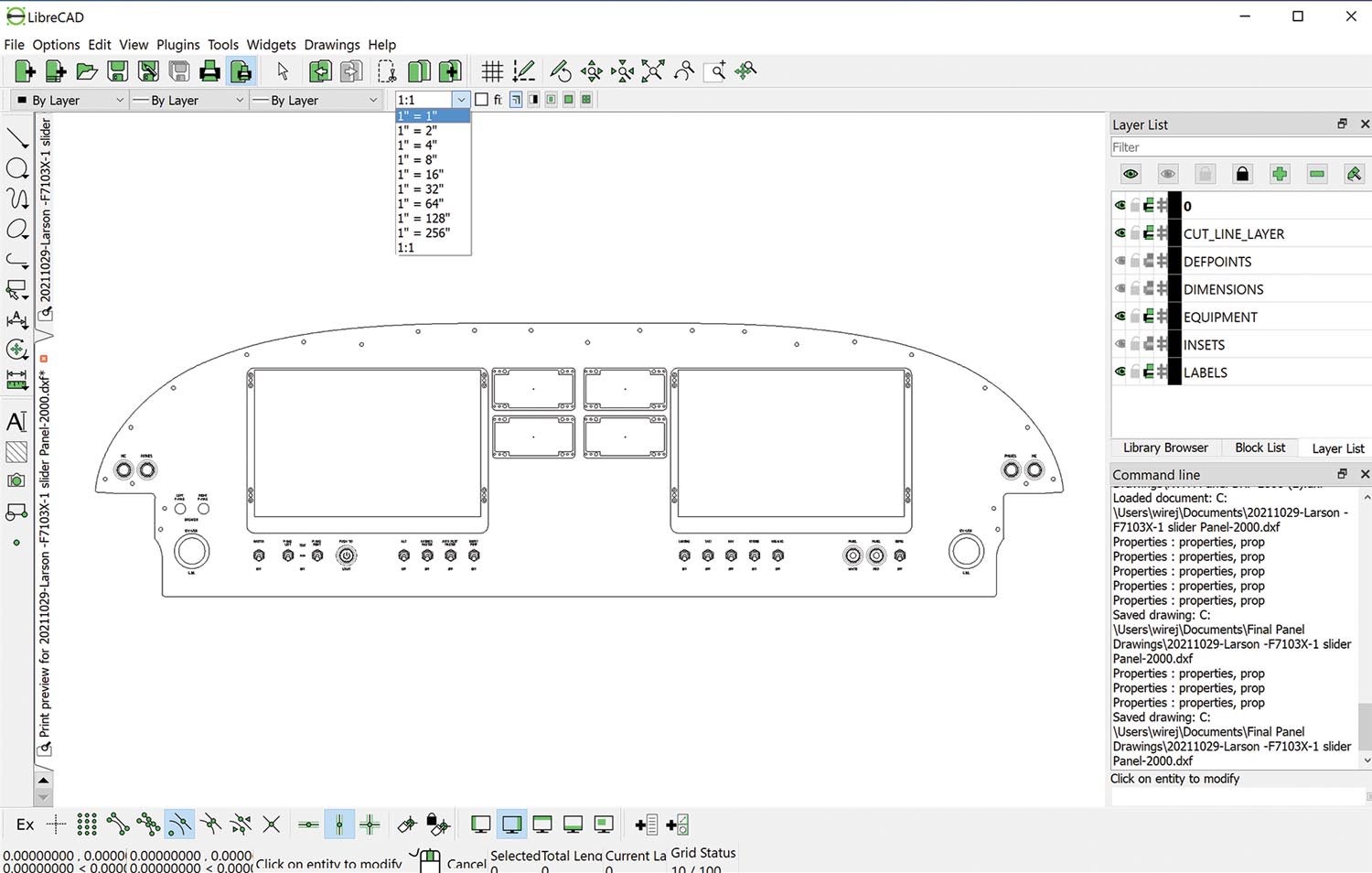
Next, you need the drawing preferences defined. To find the drawing preferences, look in “Options.” Change the paper to “A0.” This paper size is big enough to cover the size of an RV-7 panel. If you’re working on an RV-10, -14 or other large panel, you will have to modify the paper dimensions to fit. Verify the unit is set to inches and the format of the measurement is set to decimal. Select “Print Preview” and make sure there is a setting for 1 inch = 1 inch. You want the scale to be exactly the same as the drawing dimensions. The panel needs to fit within the paper. Perfect. Save it as a new file again. Yes, you will have a lot of files, but if you need to go back to a certain point, it’s very handy to have files at each major change.
Adding Layers
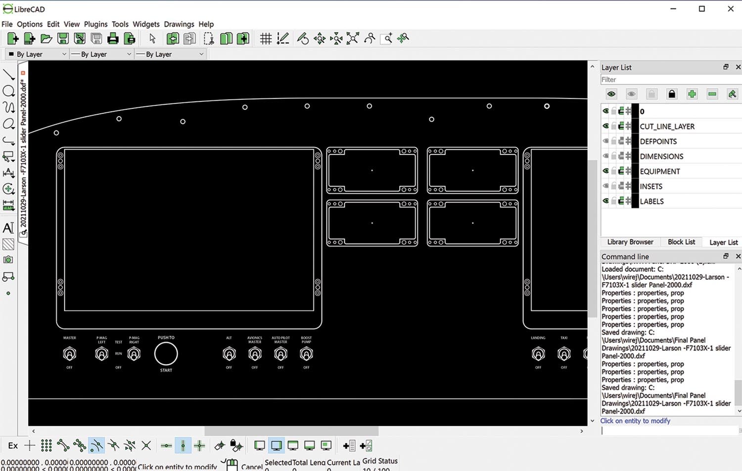
CAD drawings have a really cool feature that allows you to place stuff on different layers. This makes it possible to have tons of stuff on one drawing and only see what you want. One layer is already there. The “0” layer should be the panel perimeter and screw holes. Add four other layers for cut lines, equipment, labels and dimensions. You’ll probably need several other layers to draw everything. Feel free to add as many as you want. Set the attributes for each layer the same for now:
- Color: Black/White
- Width: Default
- Line Type: Continuous
Now draw all the cut lines and holes, but make sure you use the correct layer for each. Add crosshairs for drilling holes. They are very handy when it’s time to center-punch for drilling.
Important! Notice the CAD panel has no bend at the bottom like the actual metal instrument panel from Van’s. The drawing includes this area, so be mindful of what you place in the bottom inch. It might end up on the bottom flange.
I am fortunate to have a friend who has a CAD school degree, so I sent all my notes and drawings to him, and he worked his magic. I am happy to connect anyone who may want to employ his skills. Shoot me an email for his contact information. Since he has done my panel, he is very familiar with the issues and already has files for all the Dynon equipment, switches, breakers, jacks, etc., in CAD drawings.
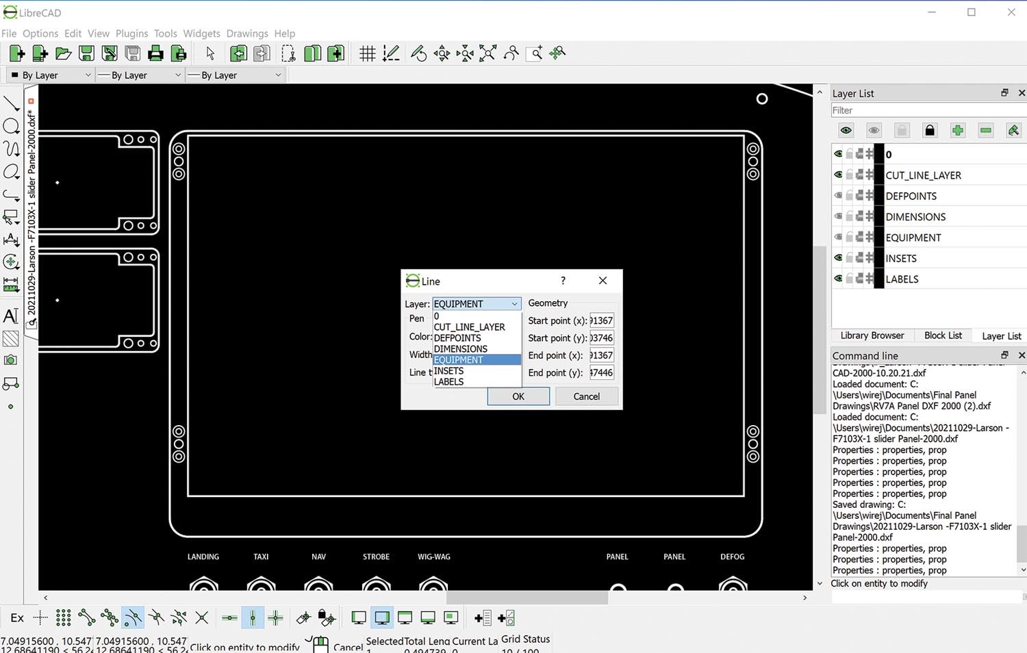
The downloaded drawings are great but typically everything is on one layer and some lines have odd thickness settings. Layers need to be changed and attributes edited for cut lines and equipment lines. Select a line and modify the attributes to change the layers. I changed all the lines for the panel bezels and the nut plate rivets to the “Equipment” layer.
Add the text for the labels on the “Label” layer. Don’t sweat the locations or the font too much. You will change that in the vector drawing (more on this later). Check layer settings by turning layers on and off. Use the “eyeball” icon to the left of the layer. Double-check layers while you are working. When you are happy with the final drawing, double-check by turning layers on and off. Check the print preview to make sure it looks correct and save it as a new file.
Delete unnecessary layers created to draw everything. You don’t need dimensions or extents, etc. Save this one as a new file. Trust me, you will be glad you have files for each change.
Here’s where it gets cool! The CAD file can also be used to water-jet or laser-cut your panel, so feel free to call around and decide how you want to cut it. The shop may want an Adobe Illustrator file, so read on. If you decide to cut it yourself, it’s not difficult, and the really cool part is you don’t need to draw on the panel. All you need is a sacrificial vinyl skin based on the CAD drawing.
Time for Vinyl
Most printing companies use CMYK printers to print on white vinyl. CMYK refers to the four ink plates used in full-color printing: cyan, magenta, yellow and black. By combining different amounts of these colors, it’s possible to create a much wider range of colors. For example, 80% cyan, 30% magenta, 100% yellow and 10% black produces a dark forest green. The combination of 5% cyan, 100% magenta, 100% yellow and 10% black produces a shade of red. How do you make white in CMYK? By using no ink at all. Instead of printing white, the white areas are actually the white vinyl underneath. This means the quality of the finished panel is dependent on how pure the printer can produce a large area of color and print fine edges for lettering.
The CMYK method is fine for trucks and signs but not great for an instrument panel inches away from your eyes. Most large areas are rarely pure color, and it’s difficult to get small fonts like switch labels to print perfectly. Don’t fret. Call around and ask local printers if they have the ability to print white on colored vinyl. Some companies have a dedicated printer that has this capability. This allows you to select a color of vinyl from the printer’s available stock and print either white or color on it. It’s far more precise and the vinyl colors are uniform.
I found a local company, AlphaGraphics, in Loveland, Colorado. Call 970-223-6316 and ask for Valerie Frost. Reach out to them for information if there are no options locally. Valerie helped with my panel and is familiar with the process.
Now you need more software and another skill set. Printers require a vector graphics file to print. Why not use a raster format like JPG, PNG or TIF? Because vector graphics allow objects like logos and lettering to be printed much more accurately. Raster formats use pixels, which often become blurry if an image is enlarged or reduced. But vector images are based on geometric shapes such as lines, points and polygons. These shapes retain sharpness when printed at any size, large or small. As for software, there are free vector graphics programs. InkScape works pretty well. Feel free to try it.
Although some printers will accept a generic SVG (Scalable Vector Graphics) file, most are going to want an Adobe Illustrator file. I recommend the Illustrator free trial, followed by the monthly subscription. You should be able to get this done in the free week, but a month or two won’t hurt too much. You may find it useful for designing your airplane paint scheme anyway. Let’s get started.
Using Adobe Illustrator
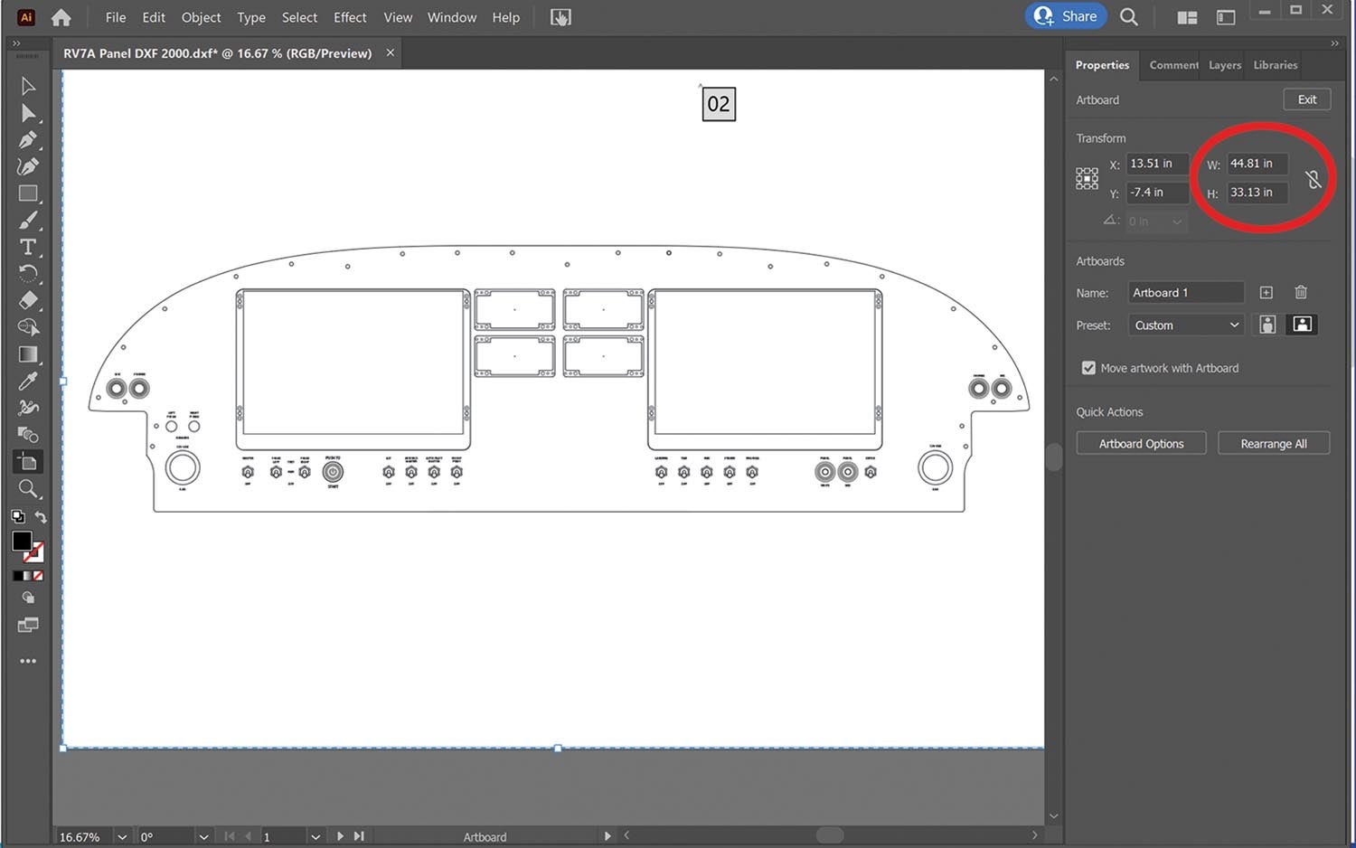
Open Adobe Illustrator and select the “Open” command. Find the DXF drawing with the deleted layers. Accept any defaults and allow Adobe Illustrator to open the file. Notice the bar on the right. Basically, they are shortcuts. Select the “Properties” tab. Set the units to inches. Click the “Edit Artboards” box. Change the width and height to the same dimensions as the paper size you changed in the drawing: A0 = 46.8×33.1 inches. If your panel doesn’t fit, adjust the artboard accordingly. Encompass the entire panel plus a little more.
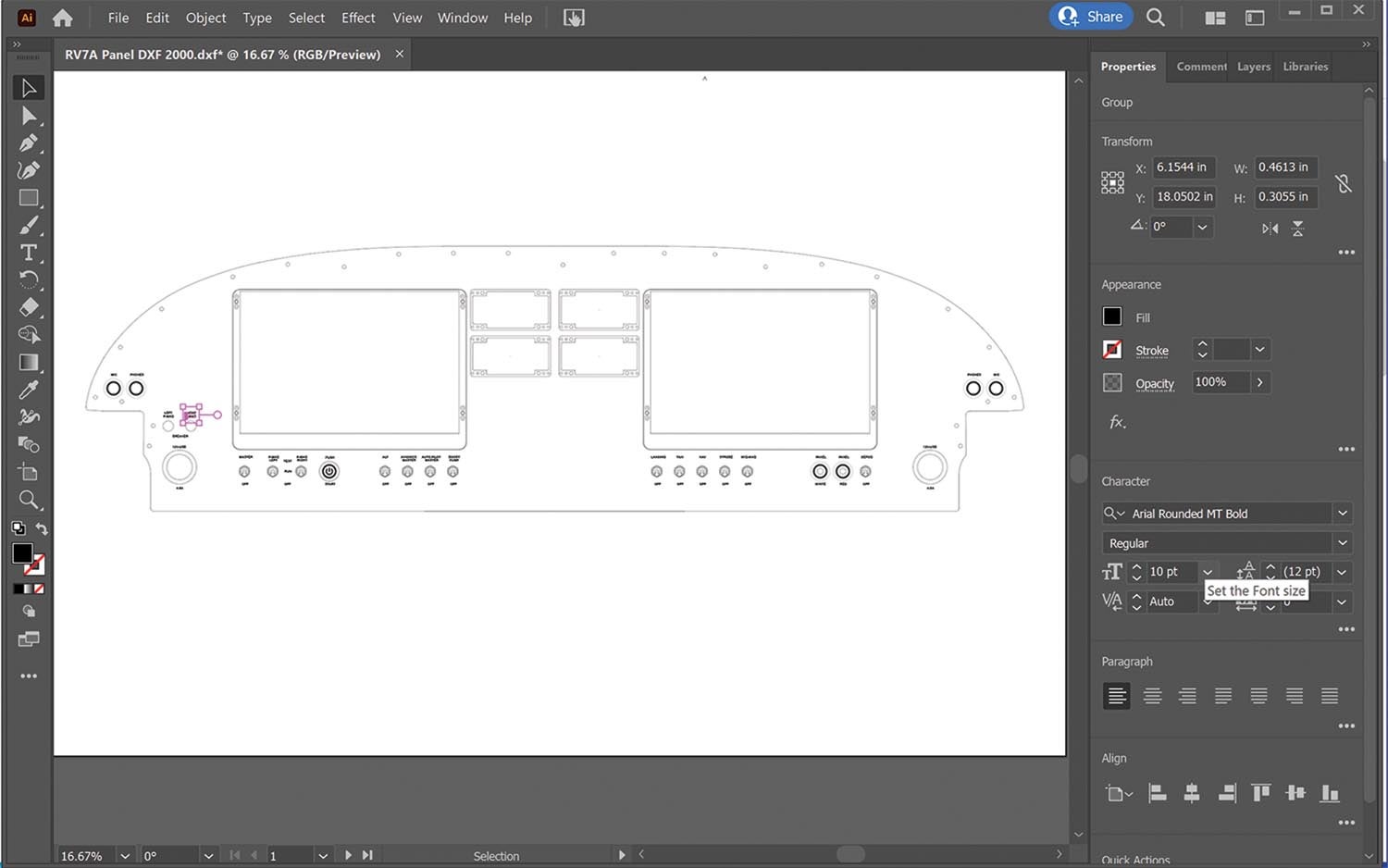
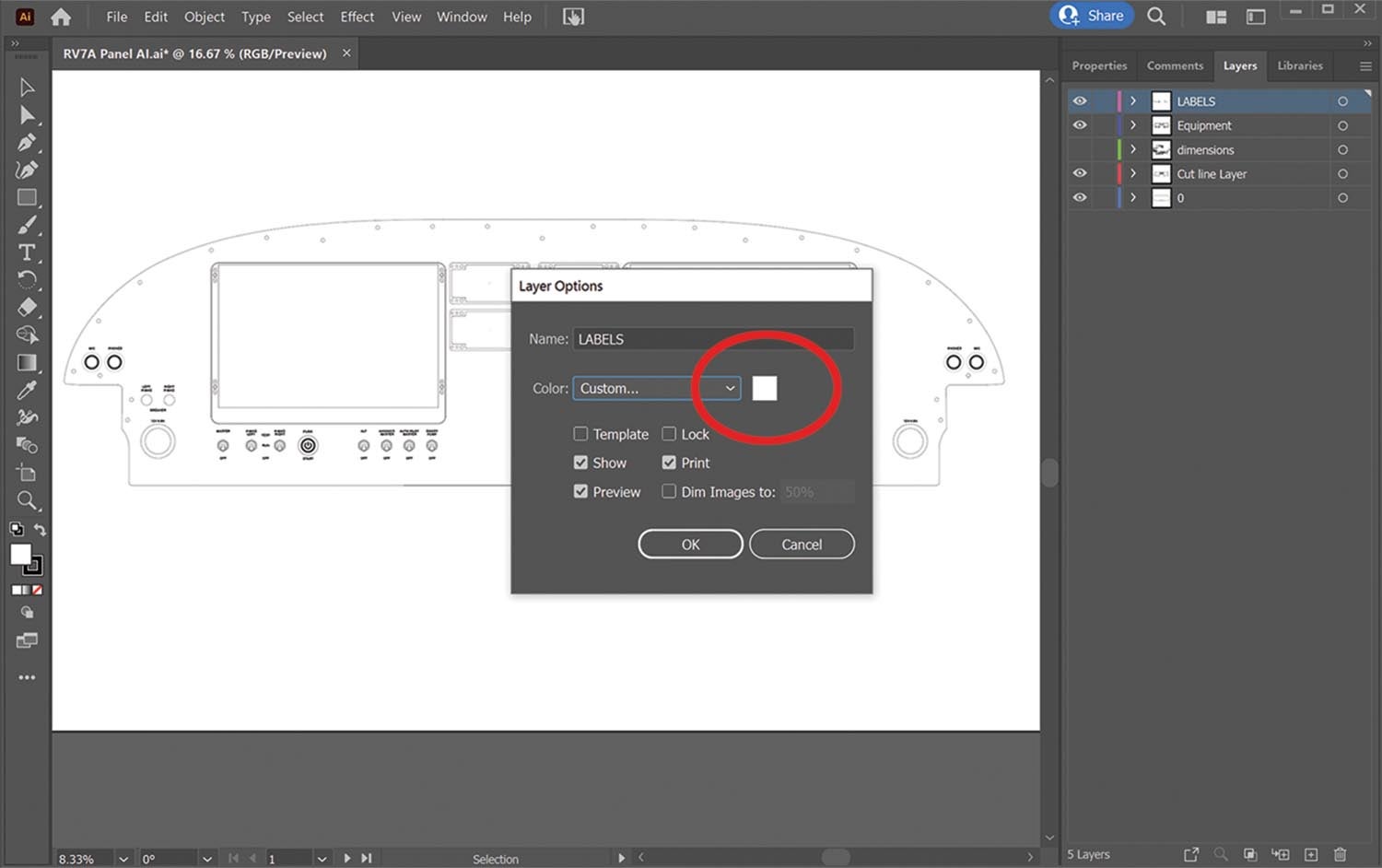
Click on the “Layers” tab. Notice all the layers from the drawing are the same. You can toggle them just like in CAD. Very handy. Make sure lines are on the correct layer by turning them on and off. You want cut lines all on one layer, equipment like bezels on another layer and labels on a dedicated layer. If you notice something on the wrong layer, select it. Click on the preferred layer in the “Properties” tab. Click on the “Object” menu. Drag down to “Arrange” and “Send to Current Layer.” If it’s visible, it will be printed, so spend some time getting it right.
Once all the layers are correct, you can adjust the labels. You want unwanted layers locked before sending the file to the printer, but they have to be unlocked to work with them. The lock button is next to the “eyeball” under “Properties” for each layer. Unlock them for now. A grid helps a lot, so click “View” and select “Show Grid.” OK, let’s change labels.
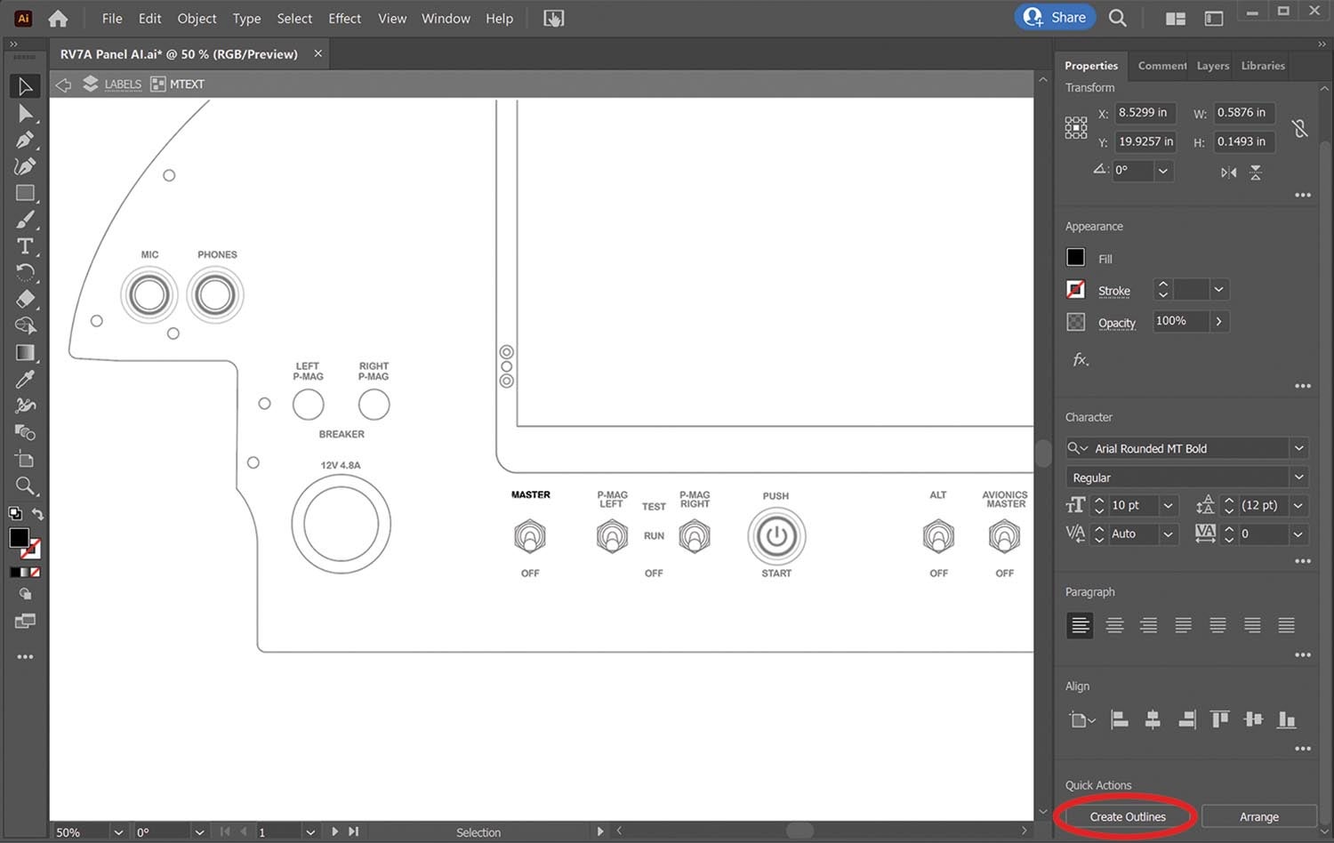
Click on a label. You can change font and size on the “Properties” panel. Selections are endless. I selected Arial Rounded M/T Bold, 10 point for all labels. My labels are “ALL CAPS.” It’s easy to change by using delete or backspace, then retype in caps. You can also move them as needed by dragging or using the arrow keys to move them in tiny increments. Adjust all the labels exactly the way you want them.
The blank EFIS areas are very useful for extra labels. Consider adding labels for things like controls. When you’re done, save it. Now it’s time to create the “printer-ready” art.
The printer does not understand fonts, so you need all the labels changed to “outlines” before you are done. Click on a label, then click “Create Outlines” at the bottom, in the “Properties” menu. Repeat for all the labels. Double-check them. Save the drawing as a new file name, just in case you need to go back and adjust something.
Finally, change the font layer colors to the color you want printed. Here’s where you can take advantage of the precision. Change the cut-line layer color to black and save the file with an appropriate name. It makes it easier to hand off a file to the printer. Have the printer run a black print on white vinyl to cut the panel. It’s a sacrificial skin. You might ask if they have any scrap jobs they can print on. You’re going to cut it all up anyway, so why not save a few bucks?
Applying the Vinyl
While you wait for the print job, buy some Rapid Tac vinyl application fluid and a stack of microfiber towels. You’ll also need a vinyl squeegee. It has a felt edge for smoothing out the vinyl without scratching. A razor knife (X-Acto) and extra blades are handy as well. Amazon is a good source for all of it.
OK, it’s time to apply some vinyl. Clean the panel thoroughly with alcohol and a microfiber towel. Clean again with another microfiber towel and Rapid Tac vinyl application fluid. The skin is sacrificial, but this is a good time to practice for the final skin application. Everything shows through, so try and get it super clean and smooth.
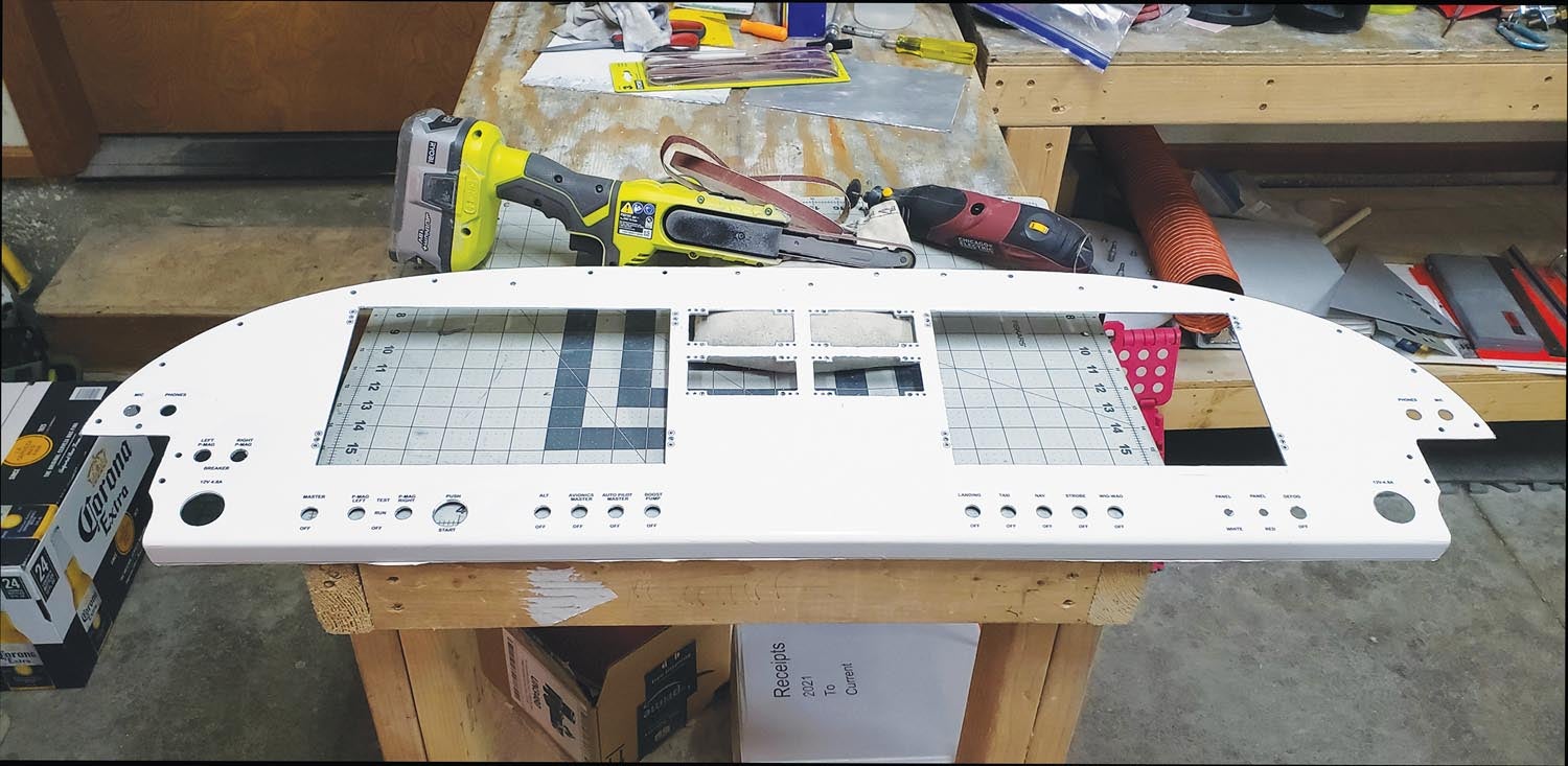
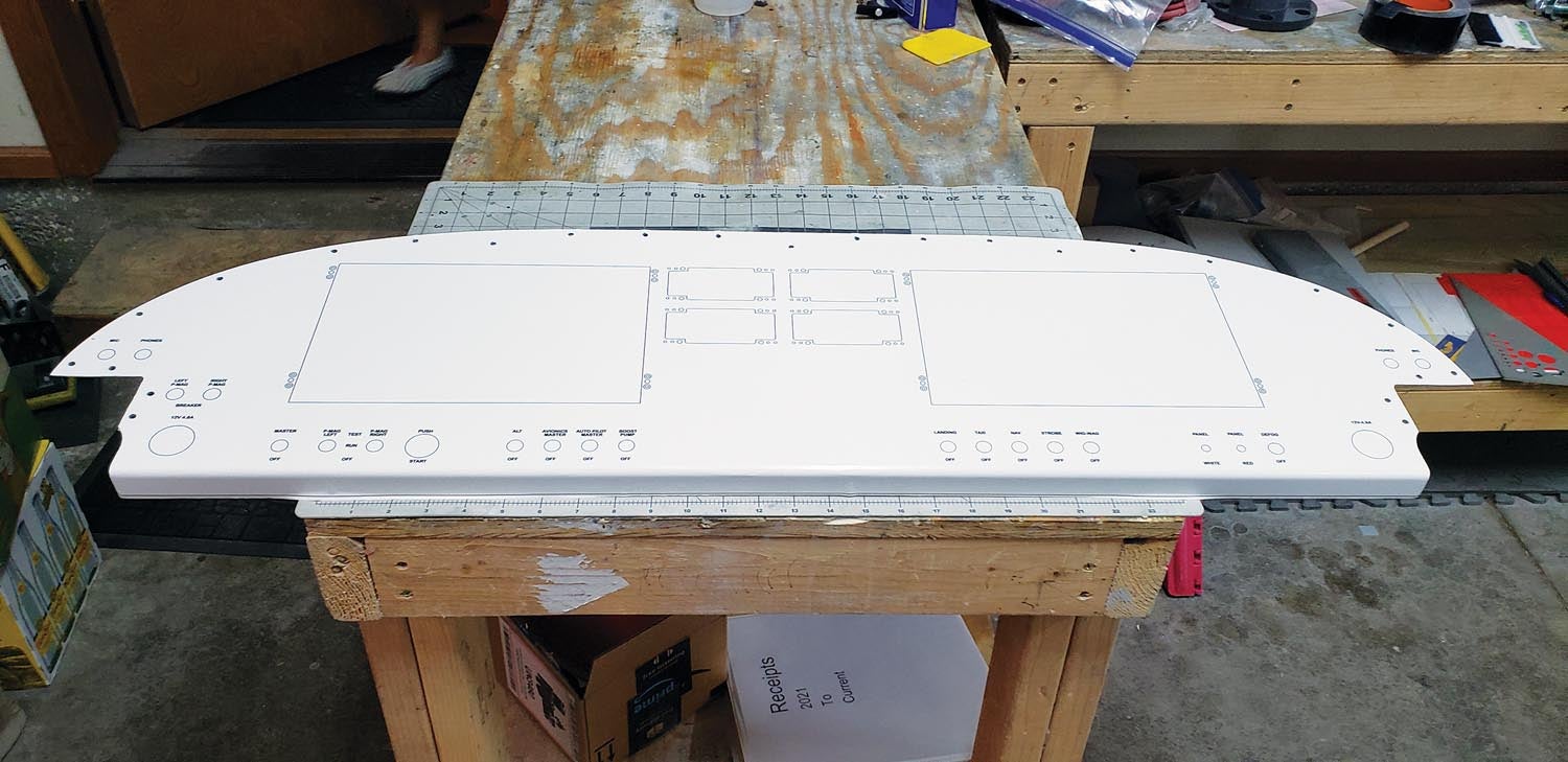
Prepunch the Van’s screw holes in the skin. You will use them for alignment. Lay the skin on the panel right side up, then flip the skin over vertically so it’s upside down laying above the panel. Spray the panel with Rapid Tac. Peel the backing a little at a time and spray the skin as well. Carefully flip the skin right side up onto the panel. Position the vinyl by sliding it around so the screw holes are perfectly aligned. Try not to stretch it as that will alter the location of the cut lines. Rapid Tac allows the vinyl skin to slide around. When it’s perfect, squeegee it down, starting in the middle and working toward the edges. If something goes wonky, peel it up and try again. Flip the panel and cut away the excess by running the razor along the edge. The rest is simple. Punch, drill and cut along the lines. Yep. Right through the vinyl. It’s a sacrificial vinyl skin. I used a Dremel to cut the slot for a jigsaw. The jigsaw made quick work cutting the box holes. Leave a little room to clean up. Final dress was done with a Ryobi mini belt sander. Edges were deburred with files. Peel off the vinyl and clean up the panel. It’s ready for the final skin.
If you prefer to have someone else cut the panel, another option is water-jet or laser cutting. I did ask a couple companies, and they wanted to start with a full flat sheet. They cut the flat sheet and make the bottom bend. Since my panel was already fit, that was a less attractive solution. You might ask before fitting the panel. The files you created can also be used to water-jet or laser cut. Ask the company rep what type of file they require for their machine.
Fitting the Final Skin
Once the panel is cut and cleaned up, it’s time for the final skin. Open the Adobe Illustrator file again and change the layer colors to the final print colors for labels and cut lines. Delete the big EFIS box lines, rivet holes and rivets. Some printers will cut the holes, and you don’t want holes where rivets should be hidden by the vinyl. Printers prefer a certain color for the cut-line layer, so ask your printer. The cutter recognizes a certain color. Save it as a new file. The big rectangle holes are easy to trim later. There is no need for the printer to cut them, and they only complicate the alignment of the final skin. The more holes, the more difficult the application.
Consider just cutting the screw holes you used earlier. A couple holes along the bottom may be useful to align the final product, but 20 holes can be a real pain. They are easily trimmed later and a few thousandths misalignment won’t be noticeable.
The printer can print the file and apply it for you, or you can give it a go and apply it yourself. I recommend letting the professionals apply the final skin. Frank Silva at AlphaGraphics in Loveland applied mine. However, if you want to make a go of it, follow the steps for application of the sacrificial skin. Use the “wet method” with Rapid Tac. Slide the skin around until it lines up, then squeegee from the center out. The skin was done using a CAD drawing, so the holes should all line up perfectly. And the best part is, it has all the labels in place too. If you ever need to make a change, just go through the process again and have a new skin printed.
Thanks for tuning in. I’ll see ya when I see ya.
![[Credit: Radiant Technology]](https://www.kitplanes.com/wp-content/uploads/2026/04/550095_5165745cc27748a598699799d796fd94mv2.jpg?w=218&h=150&crop=1 "Radiant Technology Unveils SafeGyro")


