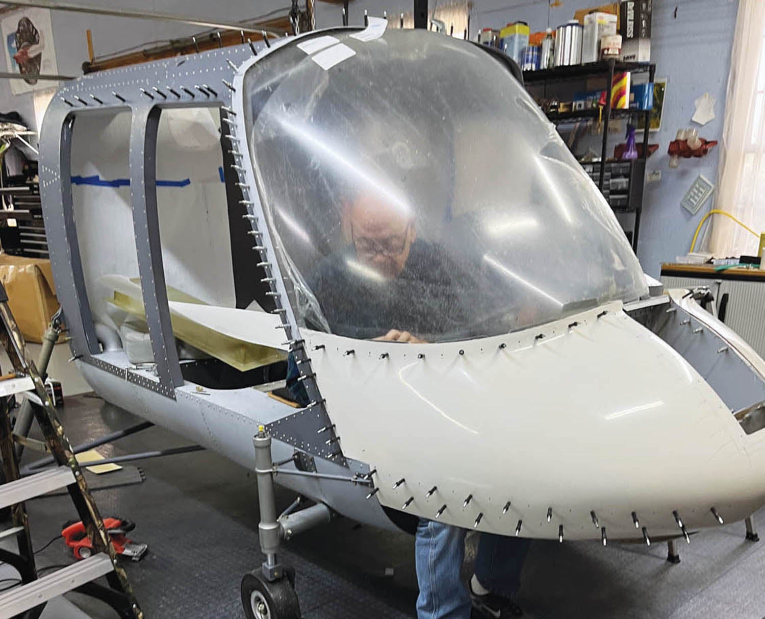
Once the helicopter lower cabin area was out of the small shop area and on its cradle, it was time to start installing larger pieces. We started with the rear cabin top, which comes premade from the factory. At the top of this unit are holes accurately drilled for mating with the transmission. That piece was large and cumbersome for the two of us to manipulate, and it had to come off and on a couple of times. But once assembled, along with the addition of the left forward skin, it was starting to look like something besides an oversized canoe.

Installing the Landing Gear
I realized the project was getting heavier as we started adding things, so it was time to start thinking about attaching the landing gear. It was already tough for Carol and me to move the lower cabin. If it got much heavier, it could be a real problem.
The landing gear is quite beefy. The Hummingbird has wheeled landing gear, with skid landing gear being an option, albeit an expensive option. I don’t have enough helicopter experience yet to know the advantages of wheels versus skids. I do know that the more expensive helicopters, including military helicopters, have wheels on them. With my H-269C helicopter, fitted with skids, it takes a dolly to move it around once I’ve landed. So, I’m hoping wheels will make movement easier, plus I’m thinking that on crowded ramps it will be easier to place some distance between myself and other airplanes prior to takeoff.
Unlike many fixed-gear aircraft that just have simple steel rods on them, all four of the landing gear on the Hummingbird have internal shock-absorbing capabilities, requiring lots of seals, O-rings and hydraulic fluid. I worked on helicopters in the Air Force (UH-1Hs and CH-3s), and I remember we used to joke about them being a big hydraulic leak, especially the CH-3s. So, I wanted to be very careful assembling the landing gear. I even replaced the O-rings that came with the kit, even though they showed an expiration date of 2029. I found some that had a date of 2036. One thing I have learned is that time seems to be going by too fast, but I digress.

It took some time to lay out all the parts and verify via the blueprints that I was assembling them correctly. They were more complicated than I thought! I used Vaseline jelly on all seals and O-rings, and once I got all four of the struts built, I put hydraulic fluid in them to prevent them from drying out. So far, four months later, there are no leaks.
Speaking of hydraulic fluid, there are lots of choices. The good old standby, 5606 hydraulic fluid, is what I have always used, and I had lots of Aeroshell 4 available, so I used that. Royco 782 has a higher flash point and is compatible with the 5606.
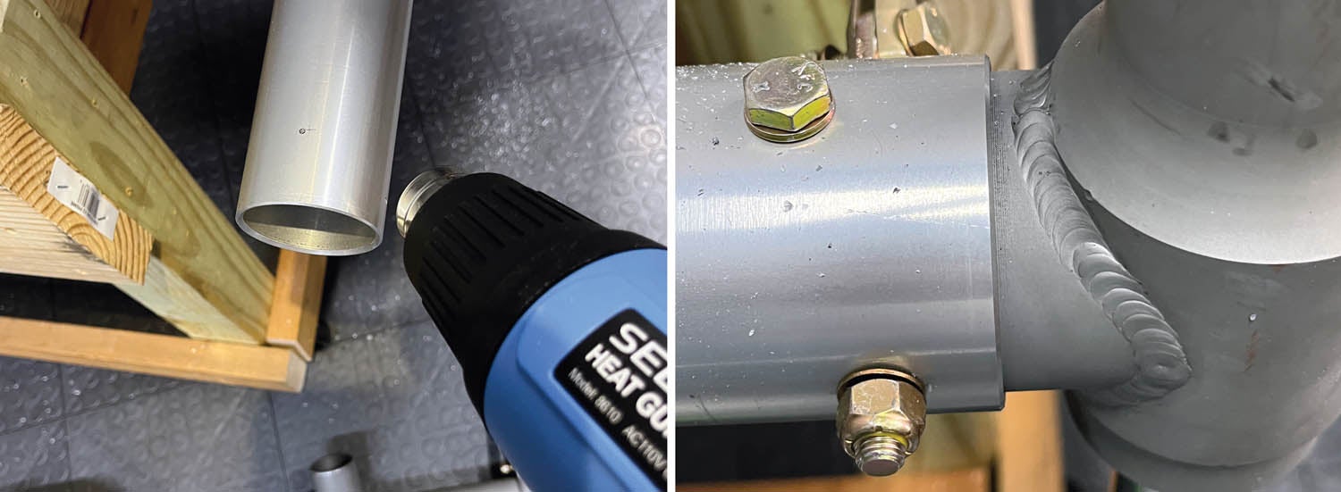
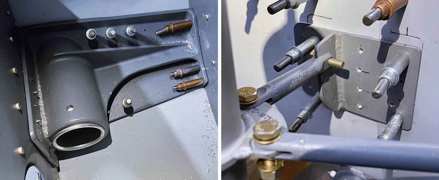
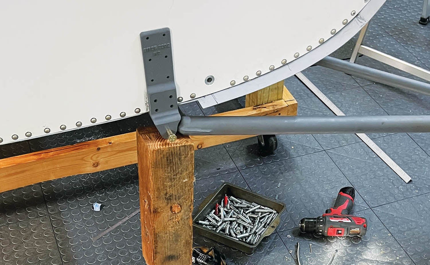
Installing the front landing gear fittings into the cabin was a little bit of work, as they required both vertical and horizontal alignment due to the castering capability. Mating the struts to the airframe gear tubes, which were a machine fit, was very frustrating until I decided to use a heat gun. Heating up the aluminum tube with the heat gun expanded it just enough so that it slid onto the gear strut quite easily. The front landing gear makes use of an internal alignment fitting instead of the typical scissors link we are used to seeing on some landing gear. It’s important that the wheels are aligned with the nose of the aircraft at touchdown and then become steerable once the strut has compressed. It was very interesting taxiing the helicopter during my demo flight, as all my helicopter flight time to date has been on skids. No taxiing possible!
It wasn’t as easy to install the main landing gear as I thought it was going to be because the cradle was in the way. It was now too heavy for the two of us to lift, so after thinking about it, I decided to buy a gantry crane. Boy, I wish I had thought of these a long time ago. It really made easy and safe work out of holding the cabin while I installed the rear main landing gear. I’ve used it many times since, as you will see. I know it will also make hanging aircraft engines easier in the future.

Skins, Doors, Windows and More
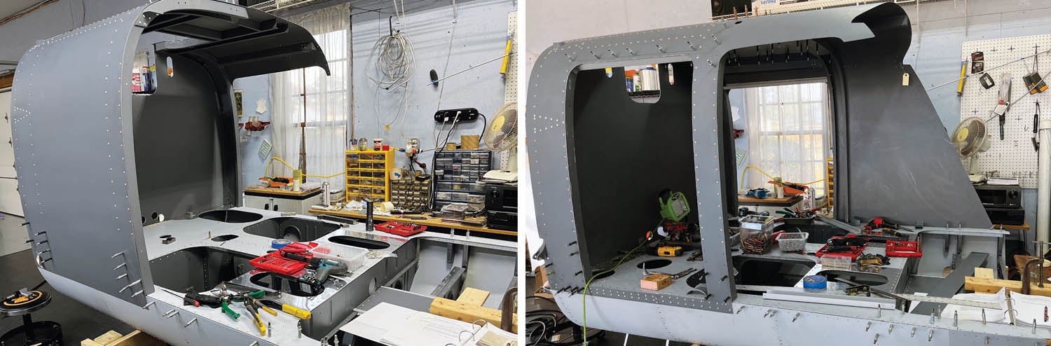
Once the landing gear was on, good progress was made toward adding internal skins, engine mounts, floor panels and even the instrument panel. The helicopter is now at a point where I can sit in it and dream about flying. The floor panels are made of the same material as the firewall—high-quality plywood sandwiched between two layers of aluminum. When riveting or bolting through this, you must be careful to not overset or over-torque the fastener in order to not crush or deform the underlying structure. Placing stainless steel thin washers underneath the rivets is done to prevent this. The front end of the helicopter had an interesting and familiar look to it when I installed it. Sure enough, it’s basically a Bell 206 front end. Even the part numbers for the windshield and chin cowl are from a Bell 206! How cool is that?
Cutting the windshields on any aircraft is always a dicey adventure. Here are some things I’ve learned over the years: Make sure the temperature is warm, at least 75 degrees or higher. The plexiglass is more malleable at these temps and less prone to cracking. I also find that using a high-speed rotary tool, such as a Dremel with a diamond cutting wheel on it, makes the job somewhat easier. Be sure to wear safety glasses! The heat from the spinning wheel melts the plastic. Take the time to smooth out all the cut sides of the glass. I have a tool I’ve used for years that works fine. Other options are to cut a “V” in a hacksaw blade or use fine sandpaper or emery cloth. Just don’t leave any sharp areas, which might cause stress risers and allow cracks to develop. When fastening the glass to the structure, always make the hole in the glass larger than the fastener so there is room for expansion and contraction of the glass. Be careful not to torque the screws or bolts too tight, and if using rivets, use “soft-set” rivets.
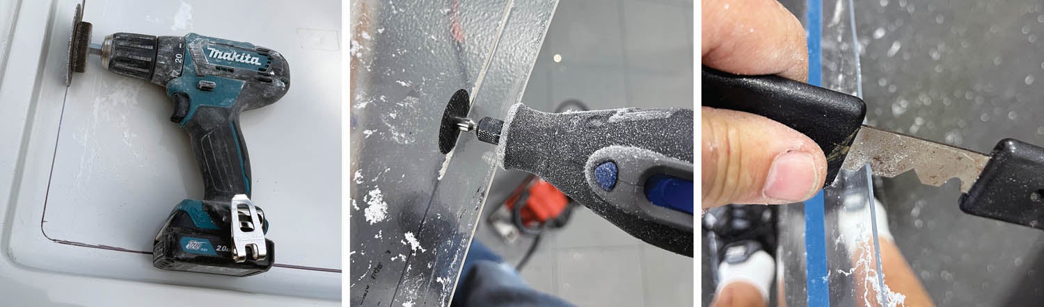
The doors are made of fiberglass and require lots of trimming and jockeying to get a nice fit to the fuselage. The top half of the doors require cutouts for the windows. Much like plexiglass, I find that fiberglass cuts better when using a rotary tool with a cutting disc.
I haven’t riveted on the internal skins yet as I think it will be easier to run all the electrical wiring first, as well as make it easier to make patterns for the interior fabric, which Carol is doing.
Adding the Tail Cone
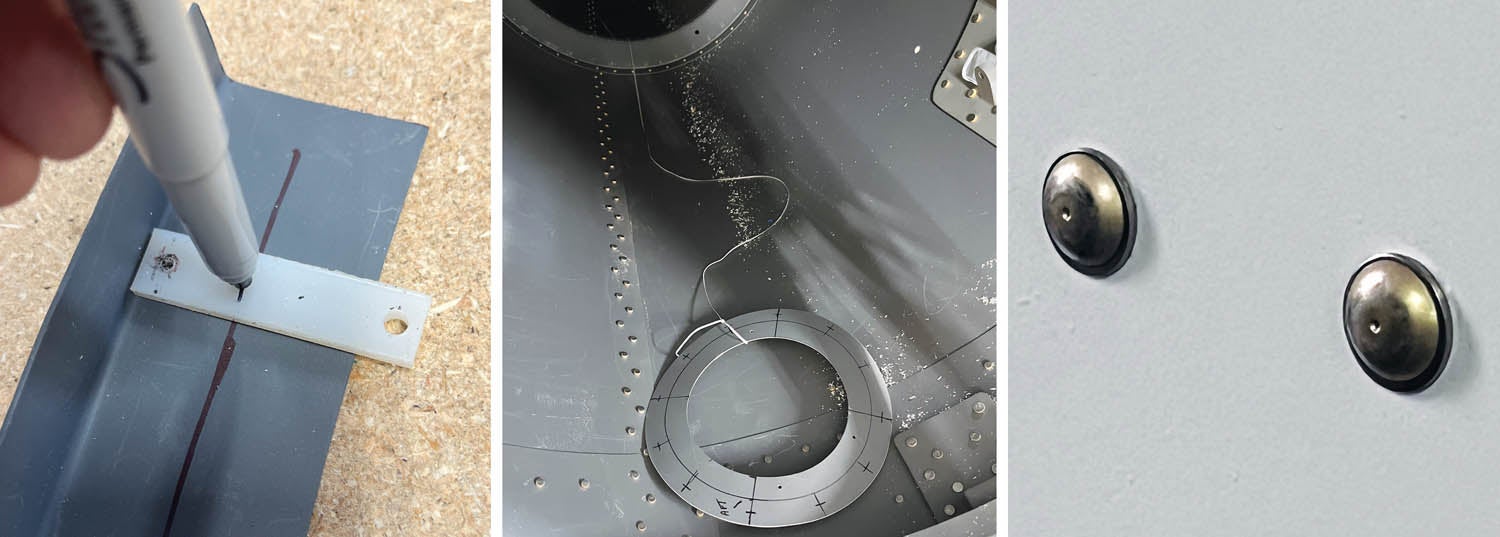
Now it was time to work on the tail cone. Yes! It might start to look like a helicopter instead of a minivan. The tail cone is supplied almost finished, having been riveted together in a jig at the factory; however, there is still a lot to do to it, such as building and installing the horizontal stabilizers. This part of the construction reminded me of building my RV-4. I had to cut aluminum from sheet, bend it, measure and drill holes, and then fasten it to the underlying structure of ribs and a tubular spar. The skin is rather thin 0.020 inch, so I had to be careful to not ding it. Another handy tool when building aircraft is a “fan spacer.” It enables you to lay out a nice line of equally spaced holes without having to do any math. A real time-saver!
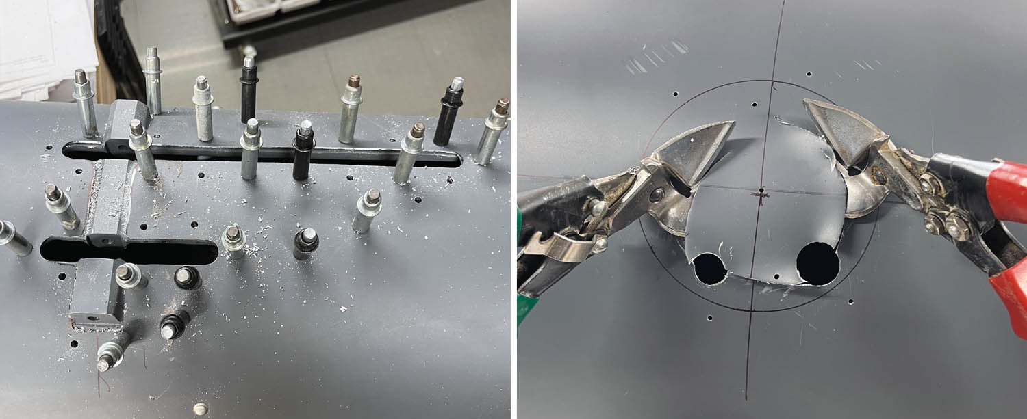
There are a couple of castings that are used to attach pulleys for the tail rotor controls that must be riveted to the tail cone structure. This also required delicately cutting out a pattern on the tail cone. For cutting sheet metal holes and patterns such as these, I find using a drill to place a hole at all corners and then using a Dremel with a rotary cutter on it works best. I also took the time to add some reinforcement plates for antenna mounts.
The gantry crane again came in very handy. The tail cone mount is attached to the cabin with four half-inch-diameter bolts, and then the tail cone is attached to the mount in the same manner. Next I had to build the vertical fin, which was done in much the same manner as the horizontal stabilizers, except that the holes were predrilled into the skin. After that came the intermediate gearbox, which is installed at the juncture of the tail cone and vertical fin.
The tail rotor drive shaft is captured on top of the tail cone by six bearings, which required a lot of muscle and lots of petroleum jelly to get them to slide onto the shaft. To ensure a straight shaft prior to securing the bearings to the tail cone, I used a taut string along the entire length. Needless to say, attaching some of the stuff inside these areas can be difficult. I managed to modify another box-end wrench to help install a nut on the aftmost bearing and convinced my granddaughter to crawl into the tail cone to help me attach another couple of nuts.
When to Paint?
With the tail cone and tail rotor now installed, it was time to move on to the control system. We covered installation in the December 2022 issue, but there’s something I didn’t mention: paint.
Because it’s a helicopter, the adage about zillions of moving parts is no exaggeration. I figured I should paint these parts prior to installation, but I didn’t have a paint booth set up yet. Luckily, the weather was cooperative, so across a Saturday and Sunday I made some parts hangers, cleaned and prepped the parts and spent 7 hours painting them on Sunday.
For those of you building your first aircraft or thinking about painting your own, just know that painting is very tedious and requires a lot of meticulousness and patience. Proper cleaning and prepping make all the difference in the outcome on whether you have good adhesion or end up with contamination causing fisheyes or other problems. At times it can be very frustrating. You will also get the chance to buy more tools, such as breathing masks, paint guns, cleaners and different sizes of tips for the spray gun. Just when you are tired from painting all day, you will have to thoroughly clean the gun and remove the masking tape off the parts without screwing up the paint.
After a lot of hard work, I had about 50 nicely painted parts for the control system. But then I realized that the inside of the cabin should be painted first, or I was going to be removing a lot of the control system parts to paint the interior later. I hate rework, and not quite everything was finished in the cabin, so I decided to jump ahead and finish out the cabin with some remaining items, such as the fuel system. Brad Clark at Vertical Aviation agreed that this was a good move.
Keeping the Momentum Going
This pretty much brings you up to date on where I am in the project. Things are moving along quite nicely, and as I’ve mentioned before, the way to keep up a cadence on an aircraft build is to try to touch it as often as possible, either physically or mentally. I still find that when I miss a couple of days, it takes a little more time to figure out where I left off. As I mentioned in an earlier column, one of the keys to keeping the momentum going is good project management and thinking ahead. As an example, paint, seats, cabin lights and other interior stuff were all ordered in advance.
Of course, there are still a lot of tasks to be done. We’ll talk about working with fiberglass, planning the panel and wiring, plus more about paint in the next installment.


