Cooling the engine and its accessories requires a continuous flow of air to come in from outside the airplane to absorb heat from the engine and carry it overboard. There are two primary goals to keep in mind when designing the cooling system for an airplane’s engine.
The first and most important goal is to keep the engine cool enough to operate safely and reliably. The second is to minimize the drag penalty of the cooling airflow. Both of these goals require the cooling system to ingest air efficiently and make effective use of all of the air taken on board the airplane.
In previous Wind Tunnel columns, we looked at heat-absorption requirements and the design of effective cooling-air inlets. We now turn our attention to managing the air as it flows downstream from the inlet throat.
Flow Within the Cowl
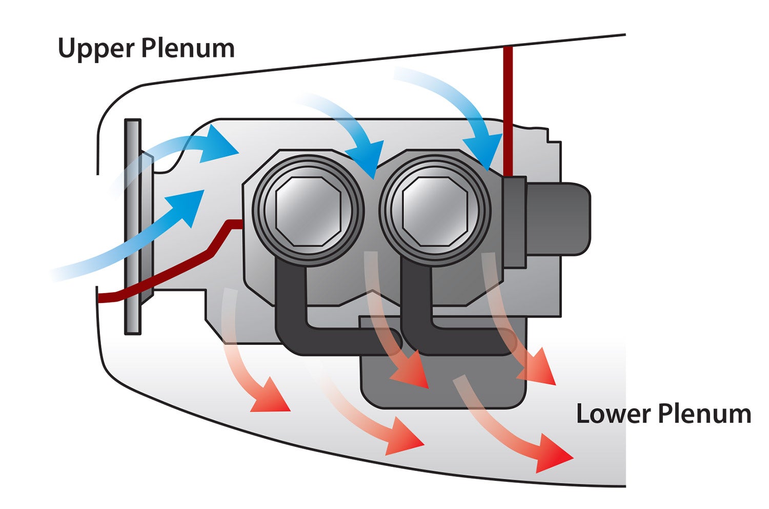
Figure 1 shows the flow path for a typical piston engine installation. After the cooling air flows in through the inlet, it goes into a plenum above the engine (the upper plenum).
The air should be able to flow cleanly from the inlet throat into the upper plenum. Ideally, the air should come to rest or nearly to rest within the upper plenum without significant flow separation or turbulence. This will maximize the pressure recovery inside the upper plenum and preserve the maximum amount of energy within the cooling air.
We have already seen the benefit of smoothly rounded inlet lips. The walls of the flow path should also remain smooth downstream of the inlet throat. The flow path downstream of the inlet throat should expand smoothly to maximize pressure recovery. Avoid sharp corners or sudden turns in the flow path.
Anything that impedes the flow from the inlets into the upper plenum reduces the effectiveness of the cooling flow. Avoid putting obstacles in the way of the airflow downstream of the inlet throat into the upper plenum.
Once the air is compressed into the upper plenum it then flows down through the cooling fins on the cylinders, absorbing heat and ending up in the lower plenum beneath the engine.
It costs drag to bring any air on board the airplane so it is important to use all of it to absorb heat and cool the engine and its accessories. Any air that flows out of the upper plenum without flowing over a hot component of the engine and absorbing heat is wasted and generates drag without contributing to cooling the engine.
Only the air that flows directly through the fins absorbs heat effectively. It’s important to ensure that all of the cooling air flows between the fins rather than flowing around the engine and its accessories or escaping through other leaks in the cowling.

Upper Plenum
Baffle Box
The most common type of upper plenum is composed of an open-top set of baffles that form an enclosure around the engine (see Figure 2). The baffles have flexible rubberized skirts on their upper edges. The skirts form a seal between the upper edges of the baffles and the upper skin of the cowling. The combination of the baffles, skirts and the cowling itself forms a plenum chamber to hold high-pressure cooling air.
This type of installation has some advantages. First, the baffles themselves are relatively simple and easy to fabricate. A second advantage is that removing the upper cowling also opens the top of the cooling air plenum, which provides easy access to the engine for maintenance.
The big disadvantage of this system is that the skirts on top of the baffles never seal perfectly. The skirts are always segmented so they can bend to seal against the cowl without wrinkling. There will be some air leakage through the slits between the segments. Also, even the best skirts do not seal perfectly to the cowl inner skin surface.
Air can also leak out through the joints between the cowl and the airframe and the inspection door for checking the oil.
All of these leaks allow a significant amount of cooling air to bleed overboard without flowing over the engine. This increases the total cooling airflow needed. The inlets must ingest enough air to actually cool the engine plus the air that is lost through leakage. The airplane pays the drag penalty for all of the air taken on board, so the air that leaks from the penalty causes drag without contributing to cooling the engine.
Sealed Plenum
Figure 3 shows the solution to the leakage problem. The cooling air inlets feed air into a fully sealed plenum that encloses the engine and has its own “roof” beneath the upper cowling. The plenum is completely sealed except for the flow path through the engine’s cooling fins.
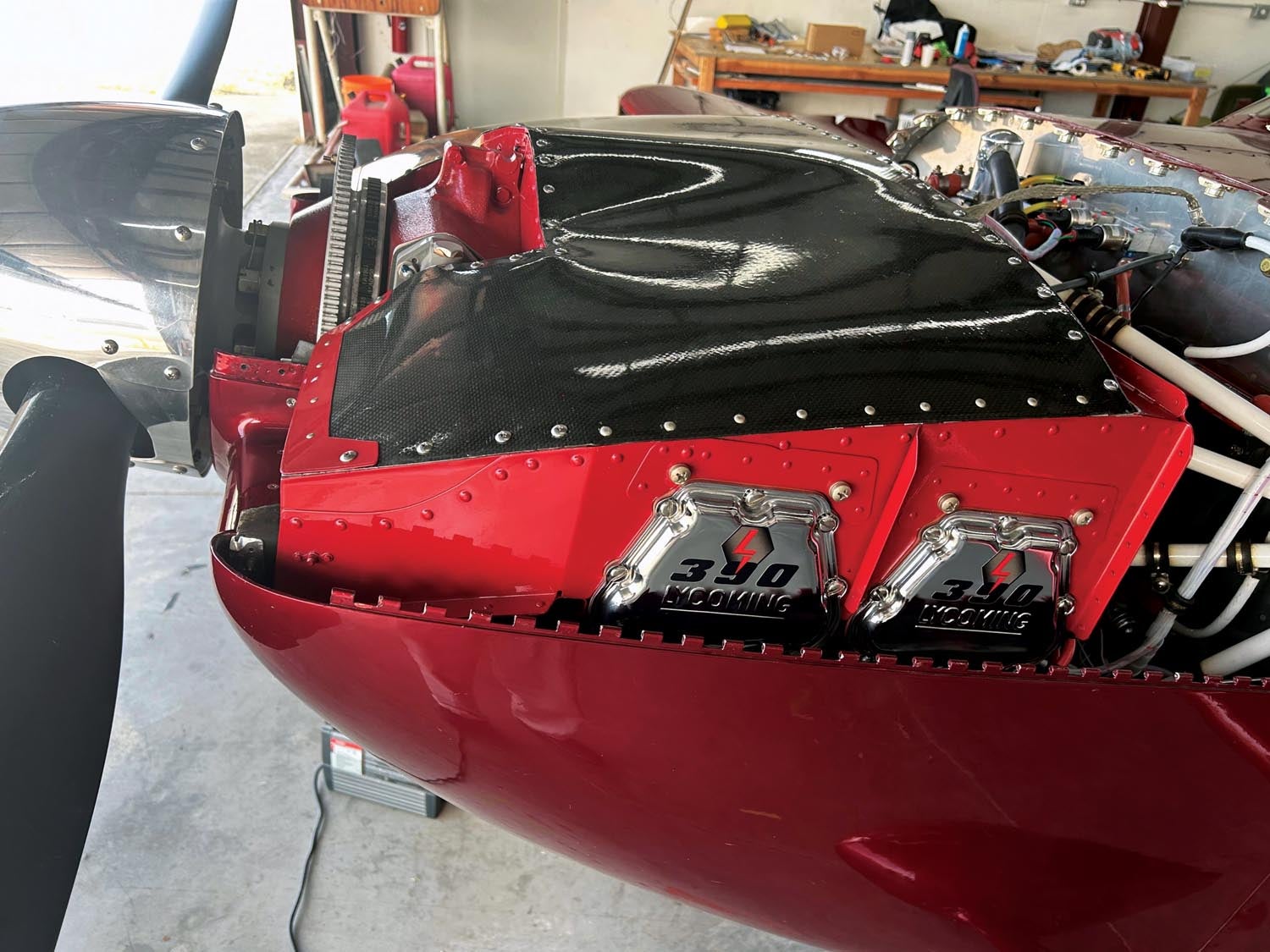
The complete plenum eliminates the losses caused by leakage around the skirts of the traditional installation. This significantly reduces the total airflow needed for cooling and reduces cooling drag.
The separate plenum approach does have some disadvantages: The plenum is a more complex part than the classic flat baffles since it must totally enclose the engine and fit within the confines of the cowling. It also adds a little weight since the roof of the plenum essentially doubles the upper cowling skin.
The final disadvantage of the complete plenum approach is that the plenum itself restricts access to the engine. This adds labor to any engine maintenance efforts since the plenum must be removed as well as the cowling to get to the engine.
Directing the Air
The cooling air should have a clear, unobstructed flow path to the cylinders. Air follows the path of least resistance. It will flow around any obstacle in its path. Any obstruction between the inlet and a cylinder will deflect cooling flow away from that cylinder. A common problem when trying to get all of the cylinders to cool uniformly is that things like wires, tubing or other items under the cowl deflect air away from some cylinders more than others.
The baffles around the cylinders should direct all of the cooling flow through the fins on the cylinders. As the air flows downward out of the upper plenum it should not have any flow path other than flowing between the cooling fins. The engine baffles should force the air to flow through the fins.
A common omission I have seen is the lack of a baffle between the cylinders of a flat-opposed engine. The spacing between the cylinders is large enough that a significant amount of air can pass between the cylinders without absorbing much heat. A simple baffle spanning the gap between the cooling fins of separate cylinders will significantly improve cooling.
Other Losses
Any air taken in through the inlet that does not go through the cylinders is lost. Many engine installations take high-pressure air from the upper plenum to cool items other than the engine cylinders. One example of this is blast tubes that direct air over accessories like the alternator. Another is an oil cooler mounted to the baffles forming the upper plenum. The blast tubes and oil cooler act like holes in the upper plenum. They take cooling air away from the cylinders and bleed away air pressure that could otherwise force cooling air through the cylinder fins.
The key to efficient internal cooling airflow is to make sure that all of the air that comes on board is properly directed to flow over a hot component of the engine and absorb heat. Leaks and other losses should be minimized.
Next month we will continue downstream and look at how to efficiently get the cooling air overboard and return it to the outer airflow.


![[Credit: LeRoy Cook]](https://www.kitplanes.com/wp-content/uploads/2026/03/DSC00008-scaled.jpg?w=324&h=160&crop=1 "Logging Time")

The height above the cylinders is also critical. Compare a Super Cub to a Scout where all other issues aside the Cub runs almost 100 degrees hotter and has several inches more space there. More modern cowling and baffles do not leave ‘dead air’ over the cylinders. I speak from experience in using towplanes where you have to be particularly sensitive to the cooling issues as each tow you go from full throttle in climb to an aggressive descent profile. With the Scout we rarely get above CHT’s of 340 (O-360) and would be happy with the Cub to not exceed 425. The magic number for descent management is 300 in preventing shock cooling and cylinder damage. Much easier to manage starting at 340. Most modern commercial designs are quite closely cowled.
Nice article. However, weight of a plenum is not a disadvantage.
My carbon plenum top is lighter than all the removed heavy silicone rubber.
Likely closer to a wash if you’ve got good composite skills.
Would you recommend high temp silicone for any holes in the baffling such as unused screw holes, spark plug hole gaps or engine mount bolt holes. Thanks I enjoyed your article
Comments are closed.