As we have seen in previous months, a longitudinal flying qualities problem can stem from either a lack of sufficient static margin or from the characteristics of the pitch-control system. If our flight tests tell us that the airplane has an acceptable level of static margin, then we must turn our attention to the control system.
Control Linkages
The linkage connecting the stick to the elevators plays a major role in determining stick forces. Stick force is a function of how far the pilots hand must move the stick to get a given deflection of the elevators. The combination of the length of the stick and the ratio of stick angular motion to elevator deflection determines this. The greater the movement of the stick grip is for a given elevator deflection, the more mechanical advantage the pilot has, and the lighter the stick force.
One way to improve a too light stick force per G is to alter the control linkage so that the pilots mechanical advantage is reduced. This will reduce the stick motion and increase the stick force required for elevator deflection.
As I noted in the February 08 column, too little stick deflection per G can be a problem. Test pilot Chuck Berthe pointed out in a letter that this is true only in extreme cases where there is virtually no stick travel (like the early F-16s). Generally, stick force per G is far more significant as long as there is some stick motion. In most cases reducing stick travel, thus increasing the stick-force gradient with elevator deflection, will make the airplane feel less sensitive to the pilot.
Elevator Aerodynamics
If the elevators have too little aerodynamic restoring tendency, the stick force required to deflect them will be small. This can cause the stick force per G and/or stick-force velocity gradient to be too low, making the airplane difficult to fly precisely in pitch.
One way to attack this problem is to change the aerodynamic configuration of the elevators to increase the amount of opposing hinge moment caused by elevator deflection. There are several ways to do this.
Elevator Planform and
Tail Aspect Ratio
The hinge moment generated by a control surface is proportional to both the area of the surface and its chord. For a given elevator area and control gearing, the smaller the chord, the lower the stick force required to hold deflection. If the elevator chord gets too small, pitch control will become over sensitive.
This phenomenon presents the designer with a dilemma. High-aspect-ratio tail surfaces are more efficient, and they give more stabilization for a given wetted area. Unfortunately, small-chord elevators tend to produce sensitive pitch control. Sometimes designers err on the side of efficiency and end up with an airplane with poor flying qualities.
Another elevator-planform problem may be excessive aerodynamic balance. It is not uncommon to put shielded horn balances on elevators, which reduce the floating tendency of the elevators. But horn balances also reduce restoring tendency, and if they are too large, this can be a problem.
Once the airplane is built and flying, it is difficult to change the elevator planform. It is particularly undesirable to change the mass balance area after the flutter envelope has been cleared. Replacing the tailplane and/or elevators to improve pitch control is a drastic measure, reserved for extreme cases. Fortunately, there are simpler ways to increase the elevators restoring tendency.
Trailing-edge Treatments
Trailing-edge shaping has a dramatic effect on the hinge moments generated by control surfaces. Small changes in elevator trailing-edge shape can have large effects on stick force and can be a powerful tool for tailoring pitch feel.
Square trailing edges: By filling in the wake on the airfoil surface near the trailing edge with solid material, the squared-off trailing edge increases the aerodynamic effectiveness of the control surface area that is farthest from the hinge, and can thus produce the most hinge moment.
This has two effects. First, the control surface is crisper and more effective. Because the wake is filled in, the surface does not have to move as far to get out of the boundary layer and cause a change in lift. Several competition aerobatic airplanes exploit this effect to improve their performance in rolling and hesitation-rolling maneuvers.
The second effect of a square trailing edge is increased hinge moment. A surface with a square-cut trailing edge feels heavier to the pilot, because the area near the trailing edge is generating more aerodynamic force when the control surface is deflected. This force has almost the entire chord of the control surface as a lever arm, and it acts to oppose the deflection of the control surface.
Trailing-edge wedges: Squaring off the elevator trailing edge will increase restoring tendency, but modifying the whole elevator to change the trailing edge shape is a large job. It is better to add something to the existing control surface to produce the same aerodynamic effect.
Fortunately, this is possible. Adding small wedges, mounted point forward, to both sides of a control surface trailing edge will produce much the same effect as chopping the trailing edge. A major advantage of using wedges is that the elevator hinge moment can be tailored by altering the size of the wedges and/or the length of trailing-edge they cover. If the control forces are too light, make the wedges larger or extend them over a greater portion of the span of the elevators. When the forces get too heavy, some of the wedges can be removed.
Most hobby stores carry pre-formed balsa intended for use as model-airplane trailing edges. This material is ideal for making trailing-edge wedges. It can be secured to the airplane with glue and/or tape for flight testing. If the total height of the pair of wedges is kept below 0.5% of the chord, they will produce little or no drag increase.
T-strips: Another way to increase hinge moment and “heavy up” control is to use a trailing edge T-strip. This is simply a flat plate attached to the trailing edge at 90 to the chord line so that it sticks above and below the trailing edge. The same effect can be achieved by adding L-shaped strips to the top and bottom of the elevators. T-strips produce much the same effect as trailing-edge wedges. T-strips have the advantage of being easy to make, install and alter, particularly on all-metal surfaces, but they produce more drag than wedges. They are also ugly and prone to damage, as they are easily bent. My preference is to use wedges.
Trimmer cord: On fabric-covered airplanes, the same effect as adding T-strips can be produced by attaching two pieces of cord to the trailing edge, one on top and one on bottom. The diameter of the cord should be about 0.25% of the chord of the tailplane that the control surface is attached to. The cord can be glued or doped to the trailing edge.
Warning: Never add T-strips or trailing-edge wedges to the trailing edge of a trimtab or the anti-servo tab of an all-moving tail. They alter both the mass distribution and aerodynamics of the tab in a way that can trigger flutter. I am aware of at least one accident in which the addition of a T-strip to the anti-servo tab of an all-moving tail caused a flutter that led to the airplane losing the entire tail.
It is important to do the same thing to the top and the bottom of the control surface. If you remove part of a wedge or strip, remove the same amount from the top and bottom of the elevator. Wedges or strips added to one side of a surface act like trimtabs and can produce large moments that may make it difficult to control the airplane. Putting them on both sides balances their effects for a desirable increase in stick-force gradient.
Make sure that anything added to a control surface is well-secured. If part of a wedge or strip were to come adrift in flight, the effects could vary from mildly annoying to downright terrifying. Remember that when you install a wedge or T-strip, you are adding mass to the trailing edge of a control surface. This can be a cause of flutter. To minimize this effect, keep the wedges or T-strips as light as possible. Even so, bear in mind that the flutter envelope of the airplane will be changed, and any flutter testing performed before the trailing-edge modification will no longer be valid.
Anti-servo tabs: Tabs are commonly used for trim. If the linkage controlling the tab is designed properly, the tab can also be used to increase the restoring tendency of the elevator. A tab geared this way is called an anti-servo tab because it acts to oppose elevator deflection.
An anti-servo tab is geared so that its deflection leads the tail deflection. If the tail is deflected trailing edge up, the tab deflects trailing edge up relative to the tail. This causes the tab to produce a down force that opposes the deflection of the tail and provides the pilot with the proper control feel.
The restoring tendency of the tail-plus-tab combination is determined by the size and gearing of the tab. Increasing the tab-deflection-to-tail-deflection ratio increases the restoring tendency of the tail, making the control feel heavier. Increasing the size of the tab has the same effect. The gearing can be adjusted to tailor the control forces of the airplane to a desirable level. The anti-servo tab can also serve as a trimtab. If the linkage that determines the tab deflection is made controllable by the pilot, the neutral position of the tab can be adjusted in flight to adjust the floating deflection of the entire tail. Like all trailing-edge tabs, an anti-servo tab on an all-moving tail can be a major cause of flutter. It is extremely important that there be no slop or play in the tab linkage.
While anti-servo tabs are most commonly used on all-moving tails, they have also been used on airplanes with conventional tailplanes and elevators.
Spring Systems
Mechanical springs can be used to
compensate for or augment the aerodynamic forces feeding into the stick. Two spring systems in particular have been used successfully.
Spring cartridge systems: In this system, springs are arranged to oppose motion of the stick in either direction. In effect, the spring cartridge is a “centering spring” for the stick. Spring cartridges can be used to increase the stick force required to deflect the elevators, and hence the stick force per G and stick force velocity gradient. It is even possible to have the springs provide all or most of the force feedback into the stick. This is routine on fully powered control systems on fighters and large transports where none of the aerodynamic forces on the control surfaces are fed directly to the pilot. Such an approach is also possible on an airplane with a mechanical control system.
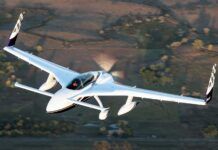
An example of such a system can be found on the Questair Venture. The Venture has unusually high-aspect-ratio tail surfaces, which cause the hinge moments of the elevator to be small, and can lead to pitch-sensitive handling. Rather than compromise the aerodynamic efficiency of the airplane, Venture designer Jim Griswold took another successful tack. The aerodynamic balance of the elevator was tuned so that the elevator had virtually no floating tendency and little restoring tendency. Springs in the control linkage provide all of the pitch control force feedback to the pilot. Chuck Berthe test-flew the Venture and the results were reported in the September 1993 KITPLANES. “Its flying qualities are much better than most certified airplanes I have flown,” he said. A secondary advantage is that there is no difference between the planes stick-fixed and stick-free longitudinal stability.
Down springs: A down spring is a spring in the control system arranged to pull the stick forward and the elevators down. Usually, a down spring is set up to provide a nearly constant force over the normal range of elevator deflection. It can help fix problems with stick-force velocity gradient and stick-free instability.
Down springs work the aerodynamic hinge moment of the elevators, which varies with airspeed against the constant force of the spring. The spring holds the elevators more trailing-edge down than they would be if the spring were not present. The trimtab is set to push the elevator trailing-edge up to oppose the spring. If airspeed increases, the aerodynamic forces on the elevator opposing the spring increase, causing the elevator to move trailing-edge up. If airspeed is decreased, the opposite happens, and the elevator moves trailing-edge down. The sense of the elevator motion opposes the change in airspeed. The airplane will have a greater tendency to hold its trimmed airspeed, and the stick force required to hold it at an off-trim airspeed will be increased.
A down spring does not actually change the stick-free static margin of the airplane, as it does not change the variation of pitching moment with angle of attack. It does produce an apparent change in stick-free pitch stability because of its effect on the change of pitching moment with airspeed. Down springs will often prove to be an effective fix. In some situations, however, an airplane with a down spring will have stick-force gradients that meet acceptable standards but will still have a dynamic pitch-controllability problem due in part to an issue that is being masked or exacerbated by the down spring.
Bob Weights
A bob weight is another mechanical device that is sometimes used to alter stick-force characteristics. It is a mass attached to the stick or control linkage in such a way that its weight puts a down-elevator moment on the stick. When the airplane is flying level at 1 G, a bob weight has the same effect as a down spring. The difference between a bob weight and a down spring is that the moment generated by the spring is constant regardless of the flight condition of the airplane, while the moment generated by a bob weight changes with load factor. Accordingly, a bob weight will increase both the stick-force velocity gradient and the stick force per G of the airplane.
Bob weights, like down springs are commonly used, and are effective in many situations. Like down springs, however, they may contribute to a situation where an airplane appears acceptable when evaluated by taking steady-state measurements, but it may still have a dynamic flying-qualities problem. J


