 The Edge Performance 912STi (a modified Rotax 912) in the SR-1 race plane is by air-cooled engine standards a somewhat complex engine. I’m sure it’s added a year to the project, due to both the inherently greater complexity as well as the extensive modifications required to package everything into the narrow firewall of the racer.
The heat exchangers—commonly called radiators—fall into both categories (added complexity, and modified). Even with a stock Rotax, you’re looking at an oil cooler, a coolant radiator and cylinder cooling fins. Folks with a 914/915/916 add an intercooler to the mix. And you’ve somehow got to get air to and from all those things.
A stock Rotax may include all heat exchangers—this varies by configuration. The oil cooler comes in three sizes—small, medium or large—and the intercooler in two sizes—regular and large. Plus, the intercooler is available with different inlet and outlet locations. The radiator only has one size.

Unfortunately, the oil cooler, radiator and intercooler all proved to be unworkable in my case due to packaging considerations. This was confirmed by playing around with placement and orientation of models of each one in the SolidWorks assembly of the SR-1. (I feel like I make a plug for SolidWorks in almost every article I write, but the subscription through EAA is really an amazing offer.) It became clear that a custom radiator and intercooler were going to be necessary. This article discusses the design and fabrication of those heat exchangers.
The oil cooler is not custom per se but based on comments from Thomas Hauklien (the owner of Edge Performance), I decided to replace the Rotax oil cooler with a high-efficiency oil cooler to help with the increased heat load that the higher horsepower of the 912STi puts on the oil as compared to a stock Rotax. (Part of this is due to the piston oil squirters that the EP mods include.) That said, this article will focus on the rad and intercooler as these were custom built to my specifications. The oil cooler was a COTS (commercial off the shelf) unit and so is not really applicable to the focus of this article.
Heat Exchanger Basics
Design of the new radiator and intercooler was based on a combination of theory and design guidelines in various books and vendor websites. Compact Heat Exchangers by Kays and London is a classic text on the subject. It’s fairly technical but a key takeaway is that cooling is approximately proportional to the velocity of the cooling flow, while power required to pump that cooling flow through the heat exchanger is nearly the cube of velocity. In other words, doubling the cooling flow velocity will approximately double your rate of cooling but the drag penalty increases by as much as a factor of eight. For this and other reasons, an “ideal” heat exchanger (from the point of view of pumping losses) is as large and thin as possible and placed in a ducted, low-velocity cooling stream. As we will see, the SR-1 radiator is far from ideal. But it fits in the cowl.
London also coauthored Oblique Flow Headers for Heat Exchangers (July 1968, Journal of Engineering Power), which informed the design of the intercooler headers. Aerodynamics of Propulsion by Kuchemann and Weber is mostly focused on intakes and ducts but since these are ultimately at the service of the heat exchanger they are certainly relevant. Popular “automotive press” publications are also great sources of knowledge, such as Maximum Boost by Corky Bell. For that matter, “Turbo” Tom Wyatt wrote a great series on turbocharging starting with the November 2004 issue of KITPLANES.
As noted earlier, the oil cooler is a stock unit, so there wasn’t anything for me to modify there. However, the vendor did supply me with engineering drawings for the various high-efficiency coolers as well as performance charts. These were quite helpful in choosing the appropriately sized cooler.

Radiator Design
The stock Rotax coolant radiator is certainly a nice, light unit but would not fit in the SR-1 cowl—it’s too wide. In addition, the locations of the inlets and outlets were problematic. I therefore came up with a core and end tank design that solved these issues in my FWF package. Frontal area is less than half that of stock, so I had to add significant depth to the core to add additional (albeit much less efficient) cooling volume. And, sadly, weight.
The stock Rotax is almost certainly a more efficient heat exchanger, given its larger frontal area and thinner core. Generally, a thick heat exchanger with a small frontal area is less efficient than a thin heat exchanger with a large frontal area, assuming both heat exchangers are the same volume. This is because with a thicker core the cooling air has already warmed significantly by the time it reaches the rear portion of the cooler. (Remember, cooling efficiency is directly related to delta-T—the temperature difference between the cooling air and the hot coolant.)
So why do I think I can get away with this smaller heat exchanger? A few reasons.
First, the stock radiator is sized for the lower airspeeds and less-than-optimal (or none at all) ducting. One can find quite a few Rotax-powered aircraft that simply hang the radiator in the breeze or stack the oil cooler just forward of the radiator (not much delta-T there!). The SR-1 will have both inlet and exit ducts, completely sealed to the radiator. As such, it will achieve better flow through the heat exchanger with lower pressure losses. Having equally distributed pressure across the face of the core is key to optimal function. Unducted cores let air spill around the edges (it’s easier for the air to go around than through) so the edges of the core contribute less cooling and aren’t (literally) carrying their weight.
Second, the SR-1 is a race plane and so is capable of providing a larger volume of air to the heat exchanger, compared to a slower airplane. Is that efficient? Not at all. Remember, it’s better to have a large radiator in a slow-moving stream of air than vice versa. But the volume of cooling air available to the radiator will be sufficient.

Third, the mass of the custom cooler, due to the nature of its construction (bar and plate versus tube and fin), is more than twice that of the stock cooler. During transient applications of power, the radiator mass itself serves as a heat sink during rising coolant temps. For short bursts of power (such as during a 3-kilometer absolute speed run), this will help alleviate spiking coolant temps. The flip side is that returning to the radiator’s steady-state baseline temperature will require some time at lower power settings, which works fine in the 3-km case, where there are a couple of minutes at low power between passes. That said, anyone familiar with this project will know that I am obsessive about weight, so the additional weight was hard to swallow but a compromise that needed to be made.
Finally, as is common with many racers, the use of spray bars for evaporative cooling is also an option if necessary. Like thermal mass, this is really not feasible for continuous-use operation but can make sense for short-term bursts of power. The FWF has been designed to accommodate spray bars for any/all heat exchangers, as may be required.
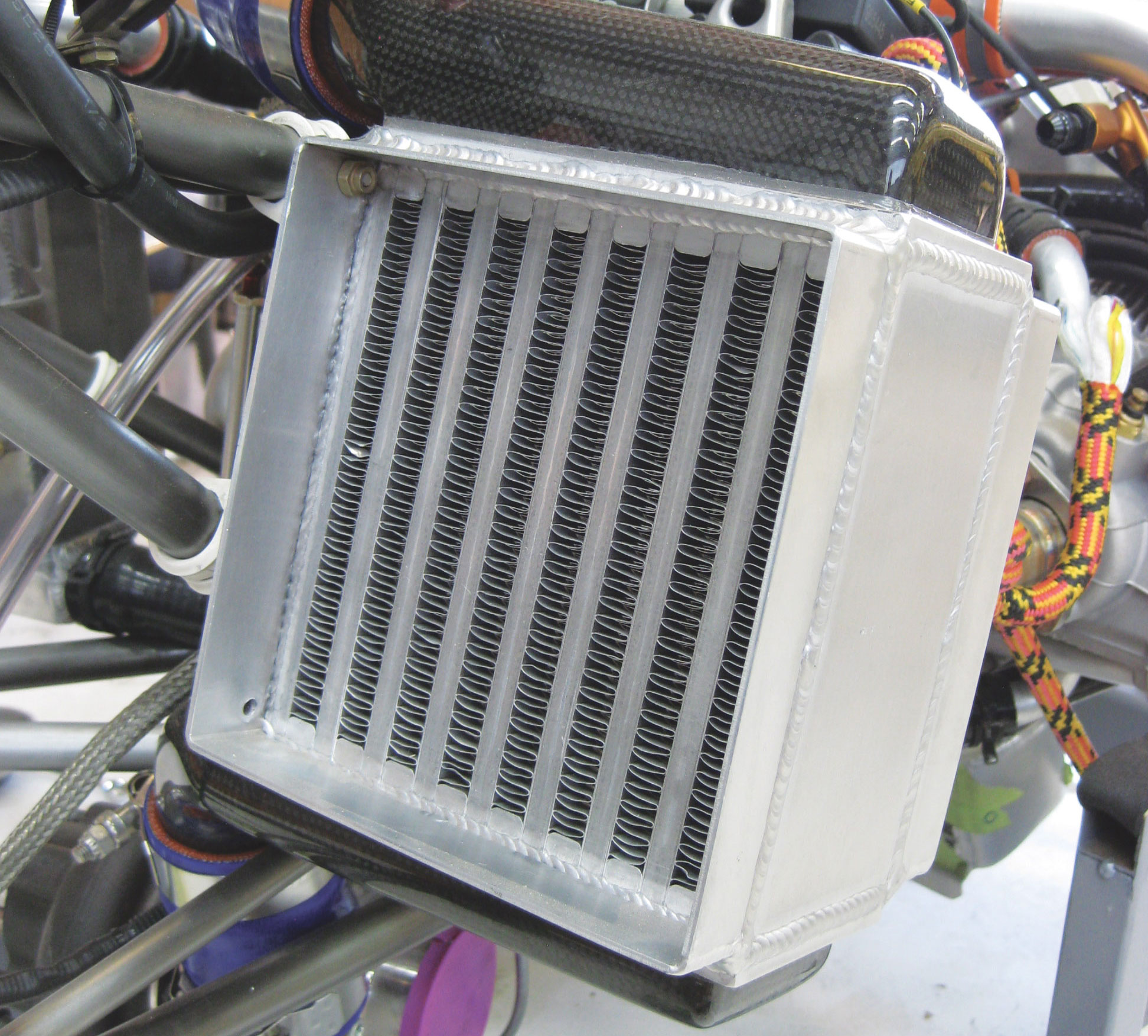
Header tanks for the radiator were basically as low-profile as possible to accommodate the necessary inlet and outlet tubing diameters, which are fixed by the mating tube diameters of the Rotax coolant pump outlet and collector. Flanges were incorporated to affix ducting. These flanges are what allow the ducting to be completely sealed to the radiator and avoid any leakage of cooling air from the system.

Intercooler Design
The custom intercooler has a similarly smaller face area than the stock intercooler and is also smaller volume. Hauklien provided the dimensions of the custom intercooler in his 912STi-powered Shark, which he said worked well. Given the Shark’s similar high speed, I felt that like the radiator, using a smaller intercooler would not present a problem as long as it was well-ducted. Likewise, should problems arise I have the option of adding evaporative cooling to improve performance.
Additionally, as compared to most turbocharged Rotax installations, the path of the air from compressor to intercooler and then throttle body is relatively short and non-tortuous. It comprises only two 90° turns (not including the 90° turns into/out of the core itself), so the pressure drop should not be terrible. This helps keep charge temps down. Long, windy charge paths require the turbo to work harder, thus increasing the charge air temp and vice versa.
Design of the intercooler inlet/outlet headers is a little more involved than the radiator end tanks, as these are subject to aerodynamic flow considerations. Ideally I would have had these machined from aluminum so that they could simply be welded to the core. The weight difference would have been small enough to stomach and as noted above, would have added to the thermal mass of the system. But these would have been quite expensive, and I felt that composite headers would be a fun challenge to take on.

Header dimensions were based on the Kays and London paper. It was also desirable to avoid unnecessarily contracting or diffusing the ducting that carries the compressed air from the turbocharger to the throttle body, as this only leads to pressure loss and increased heat. Headers were fabricated as a single-shot vacuum bagged layup in a consumable 3D-printed mold using a high-temperature resin (PT2520) followed by a post cure. The design of the intercoolers included a channel that allows the headers to be bonded to the intercooler in a manner that both mechanically locks the headers in place as well as seals them to the intercooler.
After bonding the headers to the intercoolers, the system was plugged at both ends and pressurized to check for leaks. Test pressure was based on the nominal maximum manifold pressure, multiplied by a safety factor. Note that the safety factor is applied to the pressure delta over ambient. So if your intake system runs at 1.4 bar (approximately 41 inches of manifold pressure) and you wanted to test at a safety factor of three, then you would pressurize the system to 0.4 bar x 3 = 1.2 bar, or 35 inches of mercury or 17 psi.
I first conducted the pressure tests at room temperature. Once I felt confident that there were no system leaks at that temp, I preheated the unit to 160° F in an oven, removed and pressurized it, then placed it back in the oven. Over 30 minutes I saw an acceptably slow pressure drop and considered the unit airtight and test-flight worthy.
During the room-temp pressure test, I swabbed the system with soapy water, looking for bubbles wherever I thought leaks could potentially occur. The only leaking I detected was where the silicone hoses clamped to the intercooler headers and plug caps. The maximum leakdown rate was approximately 3 psi per minute. This is magnitudes lower than would be required to affect performance, so I’m fine with this small amount of leakage.
The bubble test also proved useful in setting torque values for the hose clamps. As far as I know, most folks do these to the German torque standard (“gutentite!”), which probably works fine for aluminum headers, but I’d prefer something a bit more scientific for the carbon headers. The leak test gave me a good idea of torque vs. leakage. I gradually increased the torque on the hose clamps until I achieved the 3 psi max leakdown rate. I use this as my max inlet/exit header hose torque value and use a somewhat higher value for the other end of the hoses at the (aluminum) turbo and throttle body.

Fabrication
One skill I wish I had for this project was TIG welding. I own a TIG welder and have played around with it but it was quickly clear that achieving welds I trusted on the racer would take weeks if not months of dedicated practice. In the interest of moving things along, I’ve gone to pros for any welding of airframe parts.
I shopped around for both cores and custom rad/intercooler fabricators (if they do one, they’ll likely do the other). Some core shops only sell cores, some will also fabricate custom coolers; same with fab shops. After finding a vendor that could fabricate both the radiator and intercooler using their own cores, engineering drawings went back and forth a couple of times to make sure we were on the same page in terms of what I wanted and what they could do.

This is a really important part of the design process! If a shop or vendor discourages your involvement or suggests that because they’ve done this a thousand times, whatever they send you will be fine so don’t worry, it’s best to move on. Because most likely what they send you will not be exactly what you want, in either a minor or a major way. I could say this about so many aspects of this project—when a vendor sees you as an interferer and not a collaborator, expect a stressful experience.
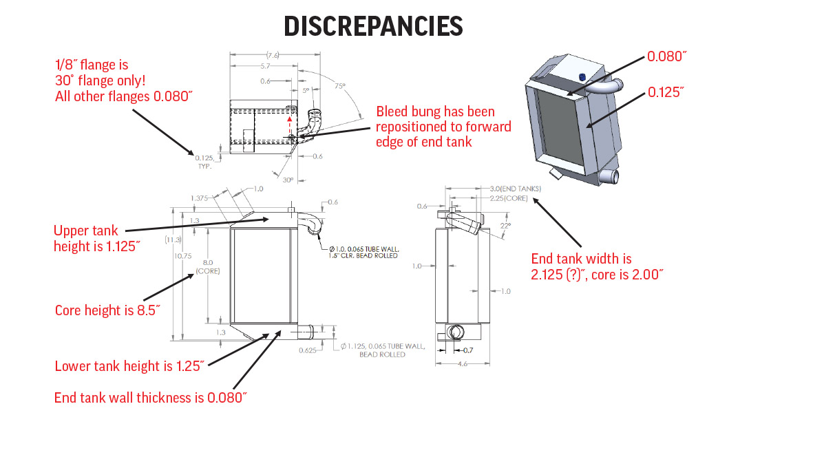
For example, I had originally spec’d the duct flanges at 0.063 inches. The engineer in charge of my project suggested 0.125 inches as more typical, which I balked at for weight reasons. We settled on 0.080 inches. This was a good compromise, as even at 0.080 there was minor warping (see pics) but at 0.063 inches I imagine it would’ve been considerably worse. Really, 0.125 inches would’ve been overkill.
The quote you get from a vendor is likely a combination of both time and materials. Anything you can do to reduce either (within reason) will lower your price. Both the radiator and intercooler had special mounting brackets that I machined in my own shop and then kitted up and sent to the vendor. In addition, the fabrication kit also included a 3D-printed assembly of the unit and 3D-printed assembly jigs to ensure that the mounting brackets and other features were correctly positioned and oriented. I also created a PowerPoint for each project that clarified how to use the jigs and other important points. It was a lot of prep work, but the two units I received from the vendor arrived exactly as designed and fit perfectly, so in the end the extra time invested paid off.
Performance?
As noted, these heat exchangers are an educated guess based on existing OEM equipment and aerodynamic theory. The point of the article is how to approach fabbing custom units. Flight of the race plane is still in the future, so performance results will have to wait. But I’ll follow up at that time and include the design of the spray bar system as well.
Incidentally, Jon Humberd tackles a lot of the same issues as presented above in his Zenith 750 SDX build. Check out Part 11 of his series in the July 2024 issue of KITPLANES for another approach to building a custom intercooler.


