
In addition to stabilizing the airplane in pitch, the horizontal tail must also trim the airplane. In steady-state level flight, the airplane flies at a constant airspeed and angle of attack. Both the pitch rate and angular acceleration in pitch must be zero. To maintain this, there must be no net pitching moment about the center of gravity (CG).
Pitching Moment
All of the components of the airplane that interact with the air produce some pitching moment. The most powerful pitching moment influence (other than that of the tail) comes from the wing. The lift of the wing acts through its aerodynamic center (AC), usually located at about 25% mean aerodynamic chord (MAC). If the center of gravity is not exactly at the aerodynamic center of the wing, then the lift of the wing will produce a pitching moment about the CG. This pitching moment will be nose up if the CG is behind the AC and nose down if the CG is forward of the AC.
Note that without the tail, the airplane would be unstable with the CG aft of the wing AC, but as we saw last month, a properly sized tail can provide sufficient stabilization in pitch so that the airplane can safely fly with the CG behind the wing AC.
The wing also generates a constant pitching moment that is independent of angle of attack. This “zero-lift pitching moment” is a function of the camber of the wing airfoil and the sweep and twist of the wing. The zero-lift pitching moment adds to the pitching moment caused by any offset between the wing AC and the airplane CG.
The shape of the fuselage can also generate pitching moments either up or down depending on the detail shape of the body. Like the wing, the body produces a moment that varies with angle of attack as well as a constant component determined by the effective camber of body.
Thrust effects can also produce pitching moment. If the thrust line does not act directly through the center of gravity, then the thrust of the engine will produce a pitching moment. This moment varies with throttle setting. The propeller slipstream blowing over the airplane also affects aerodynamics and can produce significant pitching moments.
Trim
In order to maintain steady-state flight, there must be a way to “trim out” all of these various moments to drive the net pitching moment to zero. The horizontal tail produces pitching moment by generating lift that pushes either up or down on the aft end of the fuselage. The moment generated by the lift of the horizontal tail acting on the fuselage is what opposes the pitching moments generated by the rest of the airplane to drive the total pitching moment to zero.
The pitching moment that the tail must trim out varies with the flight condition. It is a function of the loading condition, airspeed, altitude, angle of attack and throttle setting.
To trim the airplane at any given flight condition, the lift of the tail must be of the right magnitude and direction. Since the moment to be trimmed out varies with flight condition, the tail must be designed to allow the pilot to adjust the lift of the tail to trim the airplane.
Trim Mechanisms
With the airplane flying at a given angle of attack, there are two ways to change the lift of the tail. The lift of the tail is governed by the local angle of attack of the tail and the deflection of the elevators. For any given setting of the tail and elevators, the airplane will be in trim at a specific flight condition. To change the lift of the tail, either the incidence of the tail plane must change or the elevators must be deflected.
Variable-Incidence Tail
Some tail designs incorporate the ability to change the incidence angle of the otherwise fixed (forward) part of the tail. Changing the incidence of the tail changes the angle of attack of the tail and hence the aerodynamic load on the tailplane.
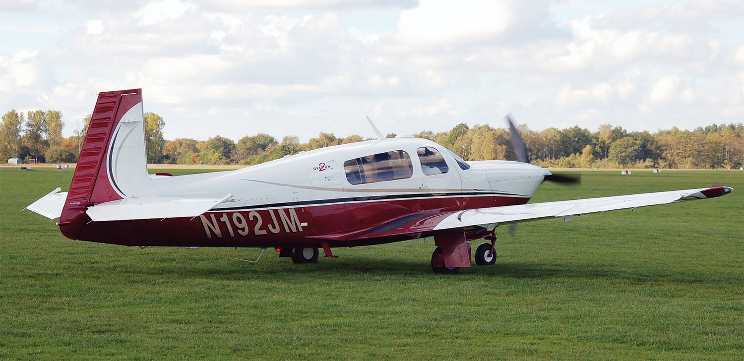
Variable-incidence tails are commonly used on large airplanes and are a feature of essentially all jet transport airplanes. They are less common on smaller general-aviation airplanes but are used on some types. A particularly interesting example is on Mooney airplanes where the entire tail assembly, including the vertical fin is mounted on a hinge that allows it to pivot up and down to change the incidence of the horizontal tail and trim the airplane.
This is a rare approach. It’s much more common to mount the tail on a cross-ship hinge on a spar (usually the rear spar of the fixed tail) and use an actuator or jackscrew mechanism to move the other spar up and down to change the incidence of the tail.
All-Moving Tail
A variation on the variable-incidence tail that uses tail incidence to trim and elevator deflection to maneuver the airplane in pitch is the all-moving tail. In this configuration the entire horizontal tail pivots in response to stick motion to change the tail incidence. The movement of the tail as a whole both trims and maneuvers the airplane in pitch.
Fixed-Horizontal Tail
Many airplanes have horizontal tails that are fixed to the fuselage and cannot be adjusted to trim the airplane. The tail is mounted at a fixed incidence chosen so that the airplane is in trim with the elevators in trail at one particular flight condition. The tail incidence is usually chosen to trim the airplane at a typical cruise condition.
To trim the airplane at any other flight condition, the pilot must deflect the elevators. The elevators, which are hinged to the fixed tailplane, act like flaps and change the lift of the tail when they are deflected. The airplane will need a constant non-zero elevator deflection to be in trim at any flight condition other than the “default” condition determined by the tail incidence.
Tail Sizing for Trim
The proper size for the horizontal tail can be determined by either stability, trim or a combination of both. The aft CG limit for an airplane is defined by stability considerations. It is the most aft CG at which the airplane has acceptable pitch stability.
The forward CG limit is often set by trim. The tail must have enough pitch authority to trim the airplane to the angle of attack for maximum lift with the CG at the forward limit and the flaps in the most critical configuration. (This is usually max flap deflection because most flaps produce nose-down pitching moments).
The tail will be sized by whichever of these considerations dictates a larger tail. On a well-balanced design, the two constraints will produce nearly equal tail size requirements.
Stick Force Trim
So far, we have seen how the pilot can adjust the geometry of the tail in flight to bring the pitching moments acting on the airplane into equilibrium. Once this equilibrium is achieved, the airplane itself is in trim.
This does not mean that the force the pilot must exert on the stick to keep it there is zero. For the airplane to be “in trim” to the pilot, the pilot must have a way to configure the airplane so that the stick force required to keep the airplane in steady-state flight is zero. We will take a look at these stick-force trim systems next month.


Mr. Wainfan,
Enjoyed your article on trim. Might I email you a longer note with some numbers outlining trim issues I’ve been working to correct on a pusher aircraft?
While I’m having some success with the direction I’m taking, a comparison with other pusher aircraft shows others have taken very different routes. Your comments on the numbers would, no doubt, provide some useful education for me and others.
Peter Cowan
A nice, concise article. I would submit one clarification where it is stated “If the thrust line does not act directly through the center of gravity, then the thrust of the engine will produce a pitching moment”.
This is only true in acceleration or deceleration- in steady state flight, the thrust line must act directly through the center of drag otherwise a pitching moment is created.
“Correction” is, in fact, incorrect.
Any force acting on an object will produce a moment about the CG unless it is acting directly through the CG.
For an airplane this is true of both thrust and drag. The thrust-induced moment is strictly a function of thrust and will be the same at a given thrust regardless of any other force acting on the airplane.
Drag can have a similar effect. If the vertical centroid of the drag is not at the CG, there will be a drag-induced pitching moment that is strictly a function of the drag, regardless of the thrust.
In the special case of steady-state level flight, Thrust=Drag. If the thrust line and the drag centroid happen to be the same vertical distance from the CG they will trim each other out.
This special case does not change the fact that in the general case they two moments are independent of each other.
Thrust will produce a pitching moment unless it acts through the CG regardless of whether the airplane is accelerating or in steady state flight.
Comments are closed.