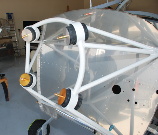
Engine mount with bushings in place in an RV-8. Note gold bushing halves facing forward on bottom and silver on top.
By this point in our firewall-forward series, we have selected an engine and prop and installed a firewall. With that behind us, the next step is to attach the engine to the airframe by means of an engine mount. Once you have selected an engine, the type of mount is already determined. You will have either a conical mount, a Dynafocal Type I or Type II mount. The Type II mount is the least common. The conical mount is typical on older engines, but the most common type of mount is the Dynafocal Type I.
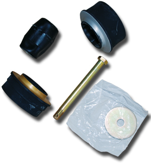
Dynafocal engine-mount bushing parts and engine-mount bolt.
You can recognize a conical mount because the engine-mounting bolts are all parallel to each other along the longitudinal axis of the airplane, and the mount bushings are rather cone-shaped, hence the name. An engine that needs a conical mount has mounting holes that are tapered from both sides and are cut square with the back of the engine case. The advantage of the conical mount is that it does not permit as much movement between the engine and the rest of the airplane as a Dynafocal type. In a tightly cowled engine, this reduced movement can be a real benefit. A conical mount will only allow about half as much movement of the engine as a Dynafocal mount.
Muting Vibration
Of course, many people think that this lack of movement is the greatest disadvantage of the conical mount, because by limiting it, you transmit more engine vibration to the airplane. The Dynafocal mount fans have obviously prevailed, but conical mounts do have their admirers. Conical mounts have the clear edge when it comes to cost. A set of conical engine-mount bushings will cost about $60, but a set of Dynafocal bushings and bolts will run about $500. Further, conical mounts are easier to fabricate if you want to make your own, because the mounts are straight instead of angled.
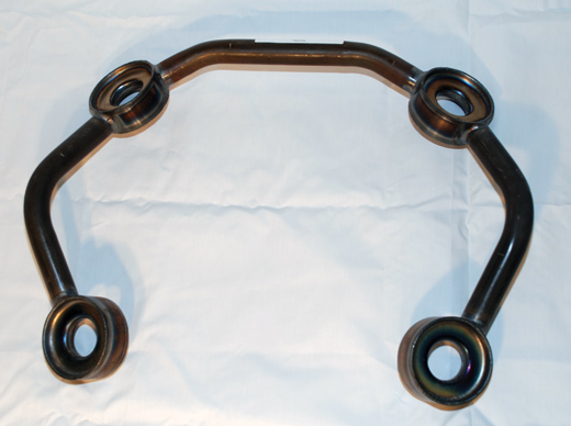
Pre-welded Dynafocal-mount rings are available from Aircraft Spruce and other aviation suppliers. These make fabricating your own mount much easier.
Dynafocal mounts are designed to minimize the engine vibration that gets transferred to the rest of the airplane. Thus a Dynafocal-mount-equipped airplane will feel like it is running more smoothly. The fact that virtually any new engine you buy for your Experimental airplane will require a Dynafocal mount shows the popularity of these mounts. They get their name from the fact that they are focused on a point out in front of the mount. In the case of the Type I mount, each mount pad is angled in at 30˚ toward this single point. For the Type II mount, the angle is 18˚. This angle makes it a little harder to get the engine installed in the mount, because each engine-mount bolt is angled inward, but it seems to work well once everything is in place.
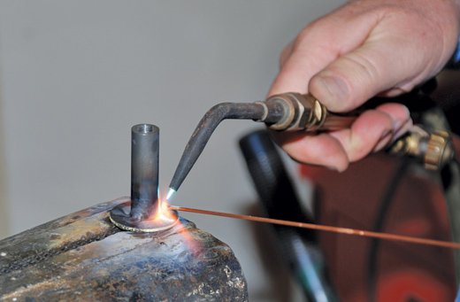
Oxyacetylene welding works well for engine-mount construction, but it is hard not to char the jig if you use wood. Pre-welding parts away from the jig can help minimize damage.
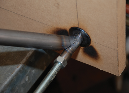
Even if you pre-weld some parts, damage to a wood jig is inevitable.
Making Your Own Engine Mount
If you are building a kit, it is highly likely that the kit manufacturer has included, or can provide at some extra cost, a complete, pre-welded engine mount to accommodate the engine of your choice. However, if you are building from plans, you will probably need to fabricate your own mount. Your choice of engine dictates the choice of engine mount for you. If your engine cases are cast and machined to accept a conical mount, there is no economical way of changing that, short of getting another engine.
Before you can begin, there are a few questions that you will need to answer. First, what type of mount is required? Second, how far in front of the firewall do you want to set the engine? It is fairly safe to assume that you want the engine centered laterally, but where will the engine go vertically, so it will fit into a cowl that will blend smoothly into the fuselage? And lastly, do you want to angle the engine away from the longitudinal axis?
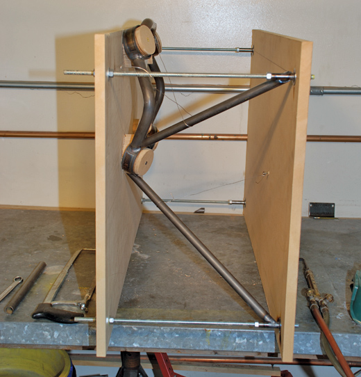
A single-use engine-mount jig can easily be made from particle board and all-thread rods. This jig is set up to make a Dynafocal mount for an RV-8.
Straight Shooting
That last question may throw you a bit. Doesn’t the engine point straight ahead? Well, not necessarily. The angle may be slight, but it may make a big difference in how an airplane flies. Angling an engine down a degree or two (or even three or four) is more common than you might think—it’s a popular way to reduce P-factor effects, especially in high-powered aircraft. Angling an engine to the side a bit is also fairly common. For example, the GlaStar engine is angled down 2.5˚ and to the right 1.5˚. Just be sure to check the design before you go assuming things. Your jig will need to take this angling into account if you are going to come up with a good result.
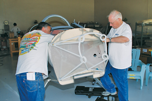
Eddie Rohwedder (left) and Ed Zaleski install a Dynafocal engine mount on Rohwedder’s Van’s RV-8. This mount will soon be supporting an IO-360 engine.
If you need to make a Dynafocal (Type I or Type II) engine mount, you can buy pre-welded Dynafocal engine-mount rings from Aircraft Spruce & Specialty, Wag-Aero or Wicks Aircraft Supply. The rings come already set in the correct relationship to each other, so you only have to fabricate the tubes to position the mount ring and weld everything together. You could do everything from scratch, but that would be a lot of extra work and not so easy to get right.
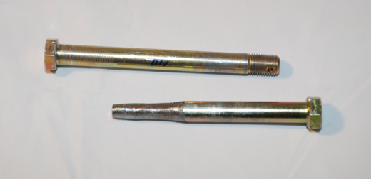
Temporary locating bolts can be helpful when you’re installing the engine mounts. An engine-mount bolt is shown at top, and a temporary tapered bolt is shown below.
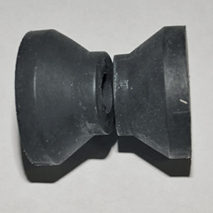
Rubber conical engine-mount bushings.
A welding jig is mandatory if you want the final result to be satisfactory. The jig can be made out of wood or steel. Wood is easier and cheaper to make, but it has some drawbacks: It’s easy to light your wood jig on fire during the welding process, or at least badly char the locating holes. This makes it much easier for things to get out of alignment. That said, many people do use wood for their jigs, but a steel jig is preferable, even though it may seem like overkill if you are only making one mount.
Material Choices
The most common material for fabricating an engine mount is ¾-inch 4130 chrome-moly tubing. A wall thickness of 0.049 inches should be suitable for lighter engines (O-235 and O-320), and a wall thickness of 0.058 inches should be better for larger engines. If serious aerobatics are anticipated, 0.058 or even 0.065 should be considered. In all cases, consult the designer for specific size and wall-thickness recommendations before moving forward. Or if you are designing your own airplane, take the time to analyze the mount for the strength that will be required. These tubing sizes are just to get you in the ballpark, not to serve as formal design recommendations.
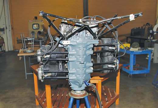
An O-290 engine with conical mounts is shown on an engine stand at Orange Coast College A&P School in California.
Many people powder coat their engine mounts after they have put them together. Generally, a light color is preferred to make it easier to see cracks that might occur in the future. A good epoxy or polyurethane paint also works well. Prepare the surface well and apply good-quality paint, because the engine compartment can be a harsh environment. If you plan to ground your engine through the engine mount to the airframe, be sure to remove the paint or powder coating from the base of the mount where it mates up to the firewall to provide good electrical continuity.
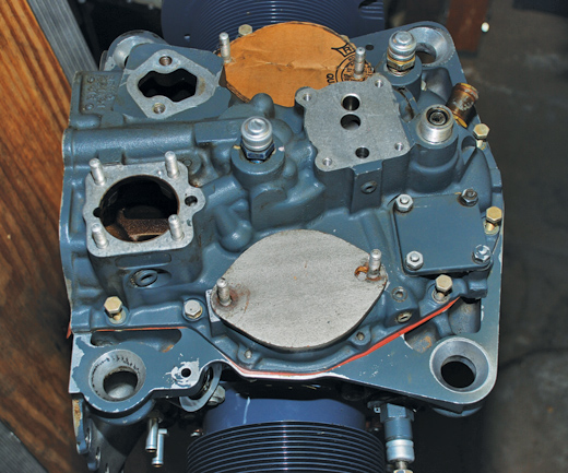
This older O-360 engine case has engine-mount holes that are tapered (cone shaped). It will need a conical mount to attach it to an airplane.
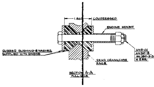
This drawing shows the proper dimension for tightening a conical mount for an O-320 engine. Tighten the bolt until the distance between the washers is 1.84 inches. This will typically require only about 40 inch-pounds of torque. Verify the correct dimension for your particular engine installation.
Gold Takes the Load
Dynafocal-mount bushings are often a source of confusion for first-time builders. Upon taking the bushings out of their packages, you will see the two halves of each bushing are not the same. One part is gold and the other part is silver, or in some cases, one half is simply thicker than the other half. The bushings must be correctly installed to avoid having the engine sit at the wrong angle. A good rule of thumb to orient the bushings is, “Gold takes the load.”
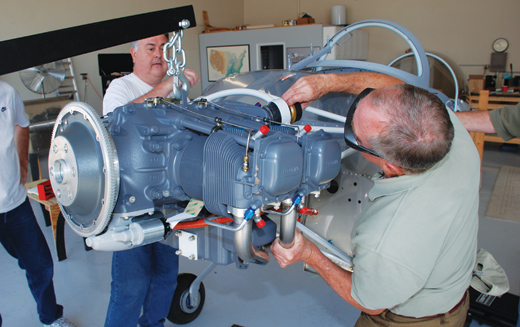
Rohwedder (left) and Richard Eastman wrestle with the engine to align mount bolts. Pulling the rear half of the bushing back from the mount can make it easier to insert the bolt.
What the heck does that mean? Look at the engine as it is set in the mount. The weight of the engine will naturally make the engine try to tip forward, thus pulling on the top mounts and pressing on the lower ones. This pulling and pushing are the loads that need to be borne by the gold (thinner) bushings. If this doesn’t make sense to you, just remember that the gold bushings halves go toward the firewall on the top, and the silver (thicker) bushing halves go toward the firewall on the bottom. With conical mounts, there is no such confusion because both halves are the same.
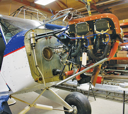
This Dakota Cub features a swing-out engine mount that makes working on the magnetos and prop governor much easier.
Once the engine-mount bolts are installed, be sure to tighten them up and torque them to the proper setting. If you are using the typical AN7 aircraft bolts and a Dynafocal mount, the torque will be 40 foot-pounds. If you are using a conical mount, you need to tighten the bolts until the rubber part of the bushings is compressed to a certain dimension, usually 1.75 to 1.84 inches. Be sure to check for the proper dimension for your particular engine installation. If you fail to properly tighten these bolts now, you may inadvertently leave them loose while fitting critical controls and/or the engine cowl. The final tightening will then cause the engine to shift and could cause problems. (Don’t ask me how I know this.)
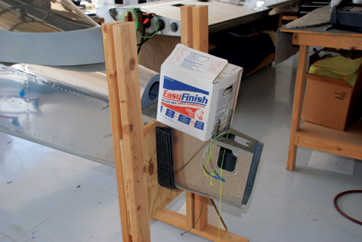
A 40-pound box of drywall mud helped keep the tail down after the engine was installed in the RV-8. Without this weight, the tail could come up, letting the nose fall forward. Be careful.
The engine is now attached to the airplane, making it look one big step closer to completion. If you are building a taildragger, be sure you have enough weight on the tail so that your beautiful project won’t end up sitting on its nose. On the other hand, trigear builders can now remove the support from beneath the tail and let the plane sit on its gear. Hanging the engine represents a big psychological step and is a cause for celebration. Go ahead and sit in the cockpit and make a few airplane noises. You’ve earned it.
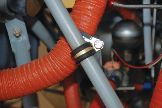
The SCAT duct is supported by the engine-mount tube with cushioned Adel clamps.
Hanging from the Engine Mount
With SCAT ducts, wires and hoses running around the engine compartment, there is always a need to secure these items to something solid, and what better place is there than the engine-mount tubes? Those tubes are strong and solid and convenient, but they also need to be protected. Chafing from poorly secured hoses or improperly installed zip ties can damage engine-mount tubes. At first they will wear away the protective finish, exposing mount tubes to rusting. If the problem is ignored for a long time, chafing can actually wear through the metal and dangerously weaken the structure of the airplane. To avoid such damage, use cushioned Adel clamps (MS21919) to secure items to the engine-mount tubes. They are harder to install initially, but they are worth the trouble in the long run.
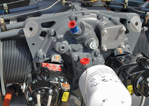
Note the angled cuts on the backside of the engine case where the mounts attach. This IO-360 engine needs a Dynafocal Type I mount.
Next time we will take a look at oil coolers, oil lines and crankcase breathers. After that we will continue to look at each system—fuel, electrical, ignition, etc.—until we are finally ready to start the engine and fly.




A very informative article, many thanks.
Just one question. No mention is made of sizes, from what I can make out thete are two, 2-3/4″ and 3-1/8. I’m putting an 0-235 into an RV3 which should I be using?
Should one need to re- tighten engine when u put new rubber mounts
Great write up, very informative and educational.
Thanks for sharing
Mick