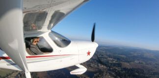
The initial flight test period of a new homebuilt aircraft is an exciting time, with lots of things to check and calibrate. Certainly one of the most important calibrations is airspeed. Although a pitot-static test can tell you that the pitot and static systems aren’t leaking and that the airspeed indicator is calibrated correctly, both the design and location of the pitot tube and static ports can introduce additional error (installation error) in the airspeed indication, and this error is also airspeed-dependent. Consequently, the only way to determine that the in-flight airspeed indication is correct is with a flight test.
Pilots have devised a number of techniques to perform in-flight airspeed indicator calibration. These methods include flying a measured course, use of calibrated in-flight equipment (flight-test pitot-static booms, towed sensors, chase planes), and the use of GPS techniques. Perhaps the most popular GPS-based method is to fly upwind and downwind at the same altitude and airspeed. The true airspeed is the average of the groundspeeds on the upwind and downwind passes, assuming the flight path is precisely aligned with the wind. Using an E6-B computer, one can then convert true airspeed to calibrated airspeed.
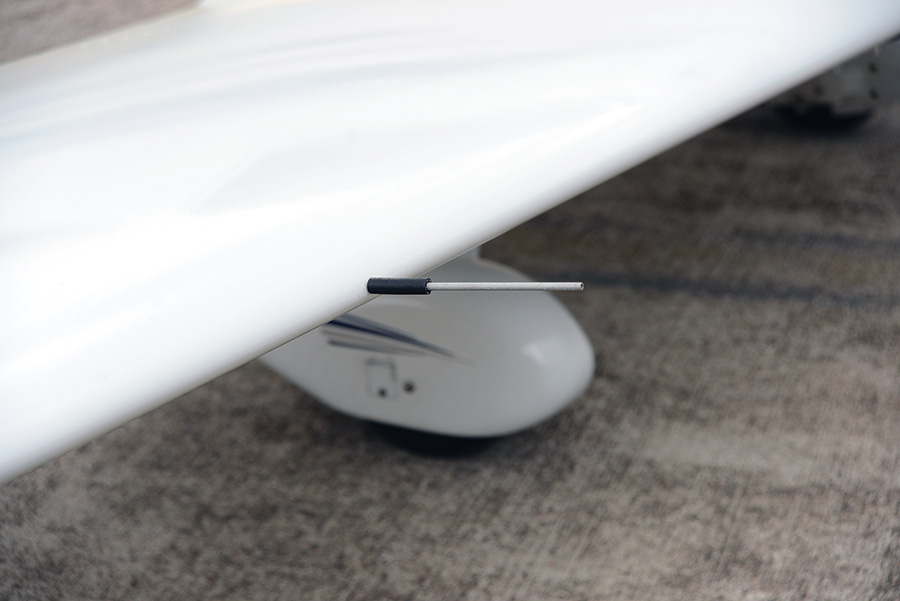
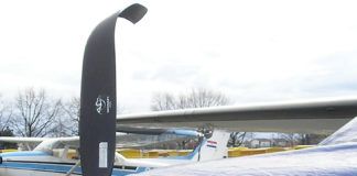
The pitot tube on the Pulsar projects forward from the leading edge of the right wing. This puts it in clear air, ahead of any aerodynamic influence from the wing. It also makes it vulnerable to damage, so care must be taken on the ground.
The pitot tube extension is attached with a short section of rubber tubing to help protect it from hangar rash.
An extension of this idea is to fly three legs at the same altitude and airspeed. The three-leg method eliminates the need to precisely align the flight path with the wind. A simple computational procedure (see, for example Advisory Circular 23-8B, FAA, 2003) allows one to compute true airspeed, wind speed, and wind direction.
When I developed the test plan for my Pulsar, I did some practice runs in a Cessna 150 and found two problems with the method. First, after turning, it takes a while for the airspeed to settle down. Second, the method does not provide any information on how well it worked. Thus, it is necessary to do multiple calibrations and average results.
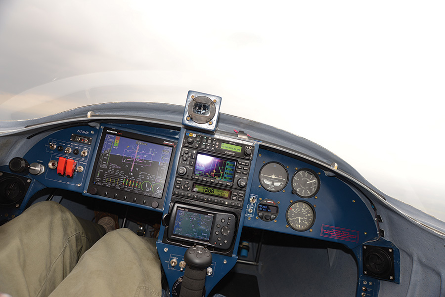
My aircraft is equipped with an Advanced Flight Systems AFS-4500 EFIS, which has the ability to record flight parameters at one-second intervals. I developed a simple computational procedure to calibrate airspeed by flying a circular ground track without the need for precise airspeed, altitude, and heading control using data from the EFIS flight log. Consequently, it was possible to calibrate the airspeed indicator on the first flight without any significant in-flight effort-I was already planning to orbit over the airfield. Additionally, the technique can be used with manual data recording, again without the need for precise airspeed, altitude, and heading control. Furthermore, this technique provides an indication of the quality of the calibration.
Collect Flight Data
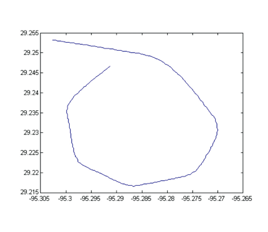
The data collection technique consists of flying four or more legs at an approximately constant altitude and approximately constant airspeed. Each leg should be of sufficient duration to allow the capture of several data points if using captured EFIS data. An example flight path is shown in Figure 1. Note that in this example, six legs of approximately equal length are flown. You should note the starting and ending time to facilitate locating the pass in the EFIS data log. The algorithm requires at least four data points, but more will improve the calibration. If recording the points manually, after stabilizing on each leg, record heading, airspeed, altitude, GPS track, and GPS groundspeed (an audio recorder is nice, but the recording workload is fairly light).
You will also need to record outside air temperature (OAT), dewpoint, and altimeter setting. If you don’t have OAT in the logs, you can estimate it using the standard lapse rate of three degrees Fahrenheit per thousand feet subtracted from surface temperature. Use the dewpoint and altimeter setting at the nearest airfield.
Computational Procedure Overview
All of the previously reported airspeed calibration methods provide a direct algebraic solution, which means they result in exactly the same number of equations as unknowns. The multipoint approach results in more equations than unknowns (many more). Consequently, rather than computing directly the values of the unknowns that solve the equations, we compute the values of the unknowns that minimize the average error. This approach is called a least-squares minimization problem.
The second major difference of the multipoint technique is that we don’t compute true airspeed. Instead, we compute average indicated airspeed error. Therefore, it is it not necessary for each measurement to be taken at the same indicated airspeed and altitude-as long as the deviation from the nominal airspeed and altitude is small, the deviation won’t significantly affect the results.
Mathematical details of the computations are reported in the paper, [Dabney] J. B. Dabney, “GPS-assisted EFIS airspeed calibration,” Earth and Space 2012, Pasadena, California, April 15-18, 2012. The mathematics are not terribly complex, but they do require a fair amount of programming. I use a technique called modified quasilinearization, but there are many numerical minimization algorithms that could be used instead.
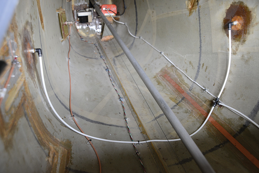
Both the design and location of the pitot tube and static system can induce errors in airspeed indication. The Pulsar static ports are located on either side of the aft fuselage.
Use the Spreadsheet
In order to make the method accessible, I developed an Excel spreadsheet that incorporates the mathematical algorithms using Excel macros. Here’s how to use it:
1. To get started, download the spreadsheet template and save it to a working directory on your PC. I developed it for Microsoft Excel from Office 2010, but it should work with any recent version of Excel. It is important that macros be enabled because the spreadsheet makes extensive use of macros. Also on the web page is a PDF worksheet you can use to record the data points and other relevant information in flight or to manually extract the data points from an EFIS log.
2. On the flight data tab of the spreadsheet, enter the data points. If using captured EFIS data, you can copy and paste from the EFIS logs for the entire flight segment. If it’s not convenient to copy and paste, manually enter one or two data points from each leg. The spreadsheet will handle up to 1100 data points, but more than 100 points will result in extremely long (several minutes) computation times. Also enter the outside air temperature (OAT, Fahrenheit), dewpoint (Fahrenheit), and altimeter setting (Baro, inches of mercury, such as 29.92).
3. Using the File menu Save As, save your data as a new spreadsheet. Press the button labeled “Press to compute calibration.” The spreadsheet will then perform the computations. The time to complete the computations will range from just a few seconds on a relatively fast computer with a small number of data points, to a few minutes for a slower computer and many data points. The algorithm is iterative, so the calibration values are updated each iteration, allowing you to watch the progress.
The Results
When the computations are complete, the section of the spreadsheet labeled “Calibration Results” will stop changing and display the final results:
IAS Corr [knots]: Indicated airspeed correction in knots. If positive, the calibrated airspeed is the indicated airspeed plus the correction. If negative, subtract the correction.
Hdg Corr [deg]: This is the average correction from indicated heading to magnetic heading. If the compass deviation in the aircraft is consistently zero and the wind is constant, this value should also be zero. If the wind is constant, the value of the heading correction is approximately the average deviation, which is not particularly useful. When the wind is not constant during a calibration pass, wind variations will tend to increase the magnitude of the average heading correction. So practically speaking, the average heading correction isn’t of much use.
Wind Dir [deg]: Average wind direction during the calibration pass. If the EFIS records wind, this value should be close to the EFIS-computed wind. You can also use estimated winds aloft to validate the computation.
Wind Spd [knots]: Average wind speed during the calibration pass.
Mean Cal Error: This is a measure of the quality of the calibration, derived from the difference in GPS groundspeed and groundspeed computed using estimated wind and corrected indicated airspeed at each data point. If the compass deviation and wind are constant, and the recording of data is perfect, the mean calibration error will be zero. In practice, a mean calibration error of two or three knots is normal, and we often see more than five knots if the wind is gusty. In extremely gusty conditions, the mean calibration error can be quite large, indicating that the quality of the calibration is low. If the mean calibration error is more than ten knots, the calibration should not be trusted.
It is common for the mean calibration error to be greater than the airspeed correction because the calibration algorithm assumes constant wind and constant compass deviation. The airspeed correction is the value that minimizes the mean calibration error. Even if the airspeed correction is zero, the mean calibration error will be fairly large if compass deviation is large or if the wind is gusty.
Example Calibration
The example data was collected at an altitude of approximately 3900 feet msl and indicated airspeed of approximately 73 KIAS in a Pulsar aircraft equipped with an Advanced Flight System AFS 4500 EFIS. The indicated (on the EFIS) winds varied during the pass between 267 (magnetic) at 30 knots and 280 at 25 knots. The ground track is shown in Figure 1. The autopilot was used to maintain altitude and the turns were standard rate (3/sec).
The calibration pass took 288 seconds. Figure 2 shows an example spreadsheet using two data points from each of the seven legs of the calibration pass. The EFIS indicated about five knots of wind gust, and the mean calibration error is about 21/2 knots. Consequently, we can have good confidence in the results.
Using the Calibrations
The multipoint airspeed calibration procedure reduces pilot workload and relaxes the requirement for extremely precise airspeed control during GPS-assisted airspeed calibration passes. It is not a substitute for ground airspeed indicator calibration, which is required for IFR certification and is a very good idea for VFR-only aircraft as well.
Special thanks to Buz Rich for his assistance in collecting test data to validate this technique using his Esqual (LS) aircraft.

