To date in the series, we have the frame of an airplane with an engine hanging off the front and lines with tanks to supply our little S-21 with the fuel it needs to fly. Tremendous accomplishments for sure, but it seems like there is so much more to do. It’s time to talk about the instrument panel and how it came about.
The time and effort put into an instrument panel’s design is a vast and very personal thing. There are plenty of mental gyrations that have to take place to create the ideal panel, one that will give you the information needed in the format you want with the space you have available. That may seem like a lot to consider in one sentence, but, well, it is a lot to consider, especially when you consider the costs involved.
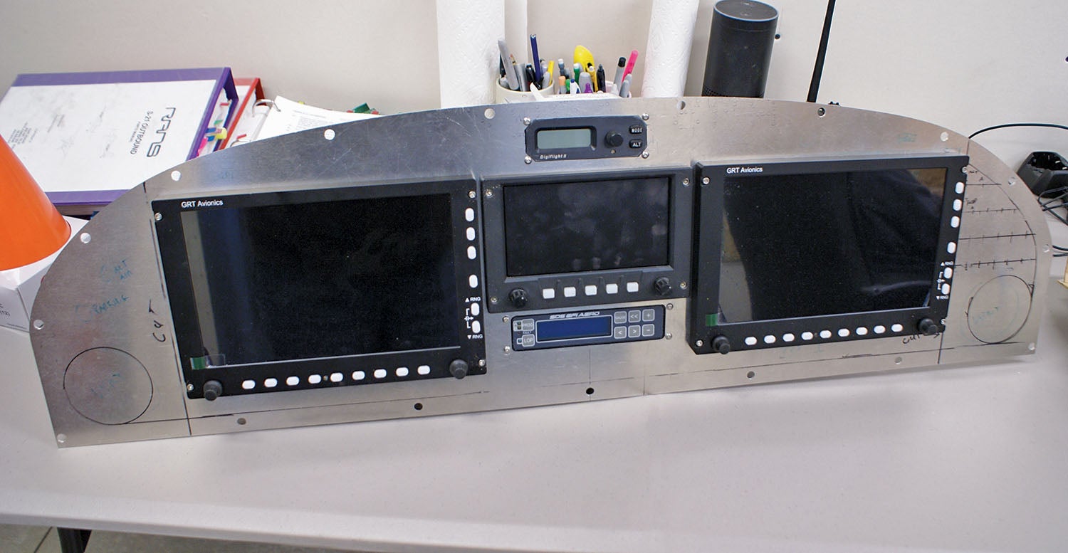
Mike’s RV-10 was well equipped, and he got spoiled with a GRT Avionics EFIS (dual 8.4-inch HX units) and an autopilot (TruTrak Digiflight II). He knew that he wanted these capabilities for our S-21 as well. I honestly also got spoiled with the glass panel as a copilot in the RV-10 and appreciated the ease of navigating, especially after becoming a pilot myself and having to revert to round gauges, maps and an iPad in our Cessna 172.
I knew that the glass panel was the way to go, but I was not convinced that GRT was the answer. I have flown with friends who have Dynon and Garmin glass panels and have been impressed with those brands. Mike, however, was insistent: He wanted to stick with GRT because the system is compatible with many other products and platforms, and he feels strongly that you get more value for your money with them. Plus, GRT’s customer service was great to him in the past. He also had done the wiring for the RV-10 and was familiar with how GRT “works,” so he was reluctant to crawl back up the learning curve with a new brand. All things considered, I agreed to stick with GRT.
New or Used?
Near the beginning of the S-21 build process, Mike began shopping the used market online for the instruments. He is quite the miser; pinching pennies is what he is all about. I am more of the “pick it out and order it” type. I figured that we are spending so much money at this point, just go for what you want. (That can be a pretty expensive attitude when you are looking at instrumentation!) Anyway, Mike was able to find an 8.4-inch GRT HX used (it’s a recently discontinued model) and a WS EFIS that he wanted to use for engine monitoring, not navigation. Problem is that he was only able to find and purchase one 8.4-inch HX used, and the fact that it’s a discontinued model made ordering a new one impossible. Of course, we wanted two of them.
As the time passed and Mike could not find another, we decided to look at the website to see what the latest and greatest EFIS GRT had available was and priced it out. I fell in love with the GRT Horizon 10.1-inch screen—oh, the resolution and functionality it had! That was what I wanted. So, we decided to bite the bullet (the money bullet, that is) and get two new GRT Horizon 10.1 displays.
One of the side benefits of using the GRT units is the ability to use them to control a remote radio and transponder. We ordered the Trig TY91 com and TT22 transponder with ADS-B from GRT at the same time we got the Horizon 10.1 EFISes. With the limited panel space available in the S-21 and us utilizing the larger space for two 10-inch screens, this ended up working out perfectly. It would fit!
There was another experience we had when Mike picked up the autopilot used online. By the time we checked it out by powering it up, we found out the screen would not light up. He worked with Andrew Barker of TruTrak to troubleshoot the issue and found out that it was a problem that could not be fixed. We ended up getting a new model of autopilot, the xCruze 100—a few more dollars down the drain on trying to save a few pennies. Sometimes it’s like that.
Honestly, though, I believe Mike saved money with his shopping online during his evening downtime. He was able to get all the wiring, connectors, fuses, switches, circuit breakers, connectors, protective “snakeskin” sleeving and pass-through grommets that we needed. Since he had done the instrument panel and wiring on our RV-10, he knew what he was in for on this job, but I had no idea how convoluted and time-consuming this part of the build would be.
Location, Location, Location
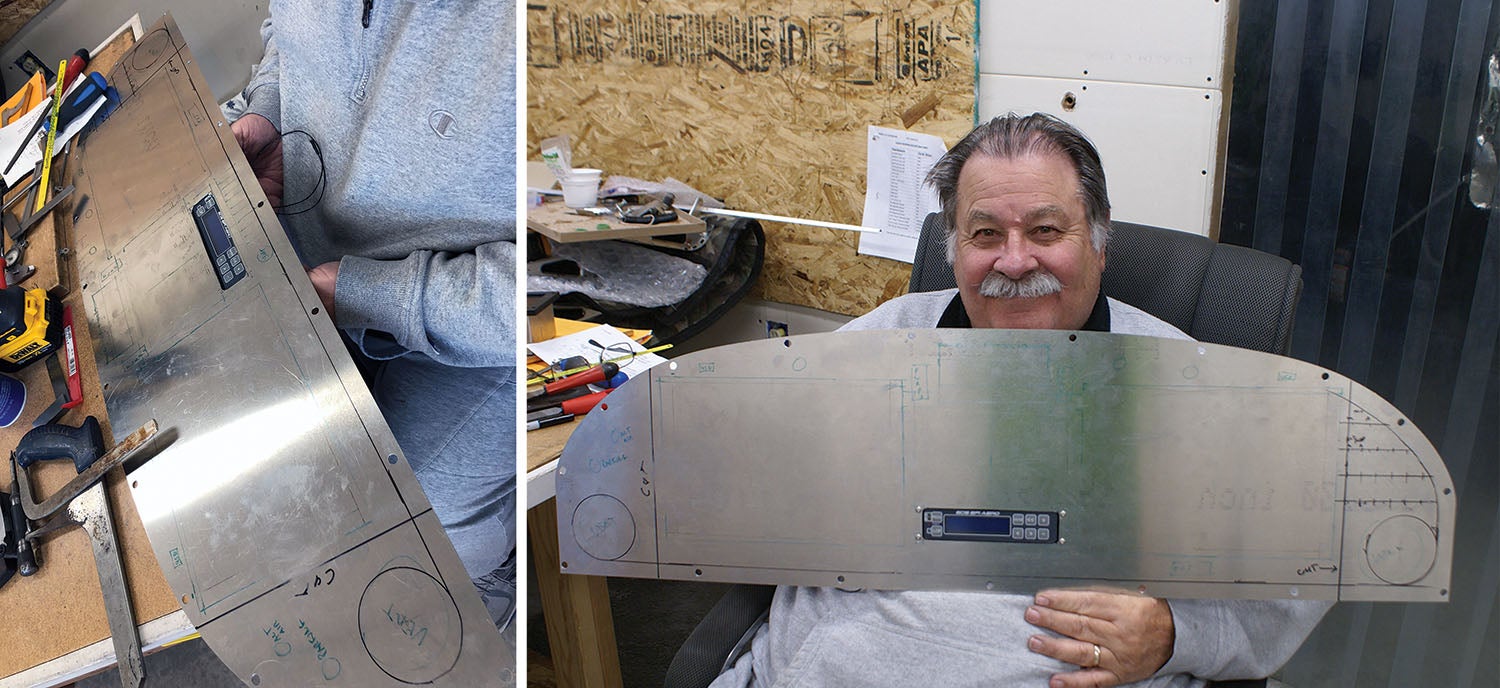
The time finally came when he was ready to design the layout of the panel. Now having the instruments on hand, he was able to draw onto the panel the exact layout desired. Mike had the theoretical ideas in his head of how he wanted it designed yet was not sure if all would fit. You not only have to consider the face of the instrument size on the panel itself, but how deep it is and where the wires are going to go—as well as knowing if there will be any support required behind the panel. Plus, you have to design for maintenance access. Once the cutting begins on the panel, you are pretty much committed!
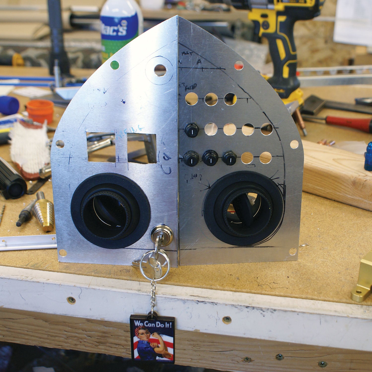
We had several discussions on where to locate switches and indicator lights. We want to have either of us fly from either seat and tried to mirror form and function on either side of the panel to achieve that end. In the long run, we decided that no matter what, if only one of us was flying, that person would be in the left seat, so we designed the panel around that concept. The key switch and other engine-related switches and such are all on the far left side of the panel. We agreed upon the placement of the instruments and switches before any cutting began.
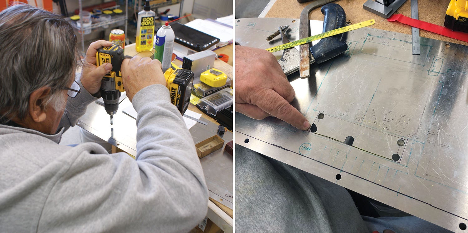
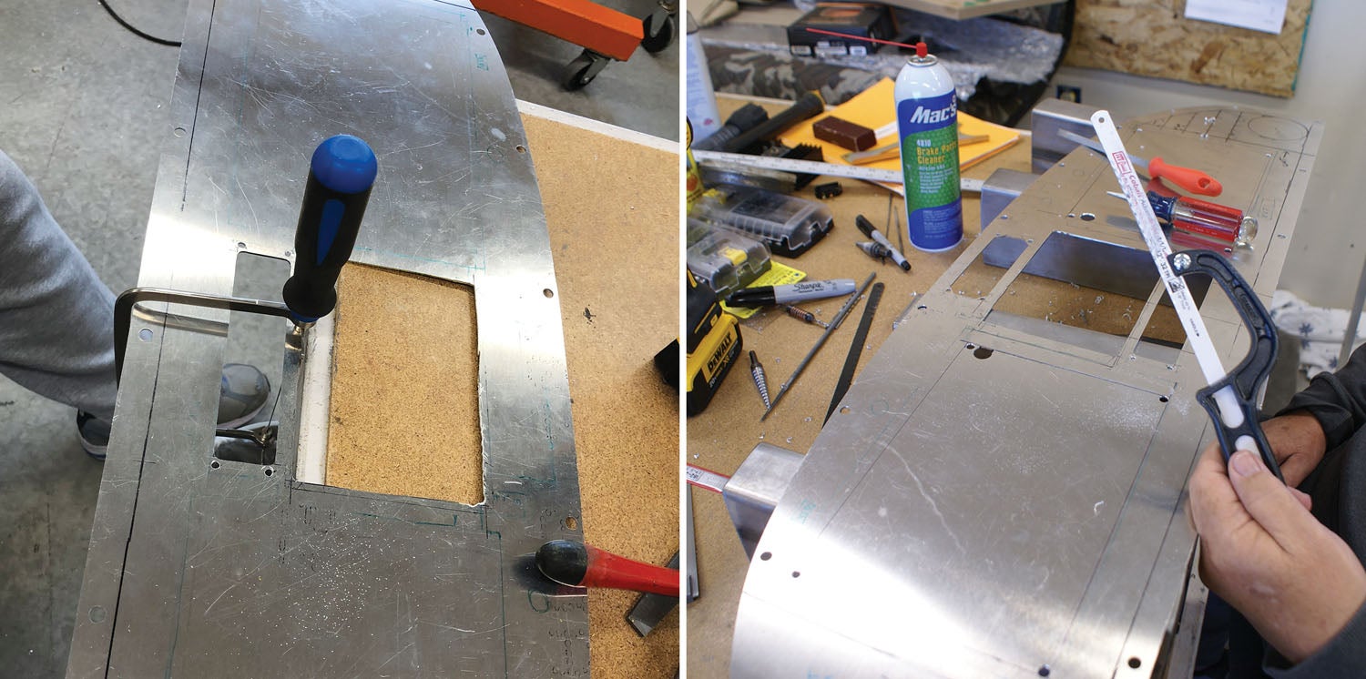
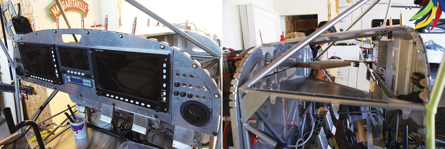
Mike drew the dimensions and exact locations of the instruments and items on the metal with a marker, leaving two lines where sections of the panel would be cut. The center section of the panel would be hinged on the bottom and screwed into the top of the panel frame to allow it to drop down (toward the seats) for ease of access. The side panels, which would remain stationary to the panel frame, contain the vents, circuit breakers and engine-control switches. (See more of this in “The Big Cut,” below.)
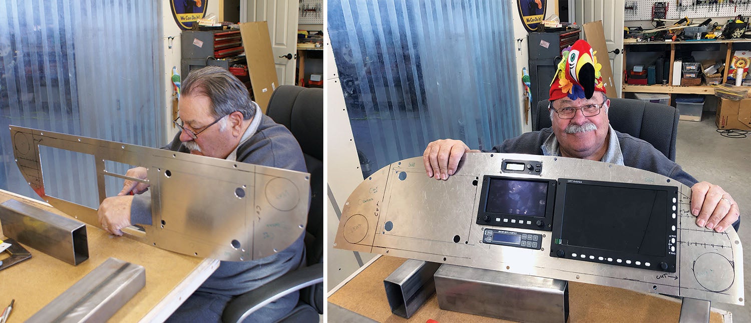
Mike was like a little boy when he was cutting on that panel, a dream come true for him! I was quite impressed at how meticulous he was with getting the instruments’ fit just the way he wanted, taking things a bite at a time and fitting the instrument several times, a bit here and a bit there until it was just right. Then repeat the process for the next instrument.
Moving In
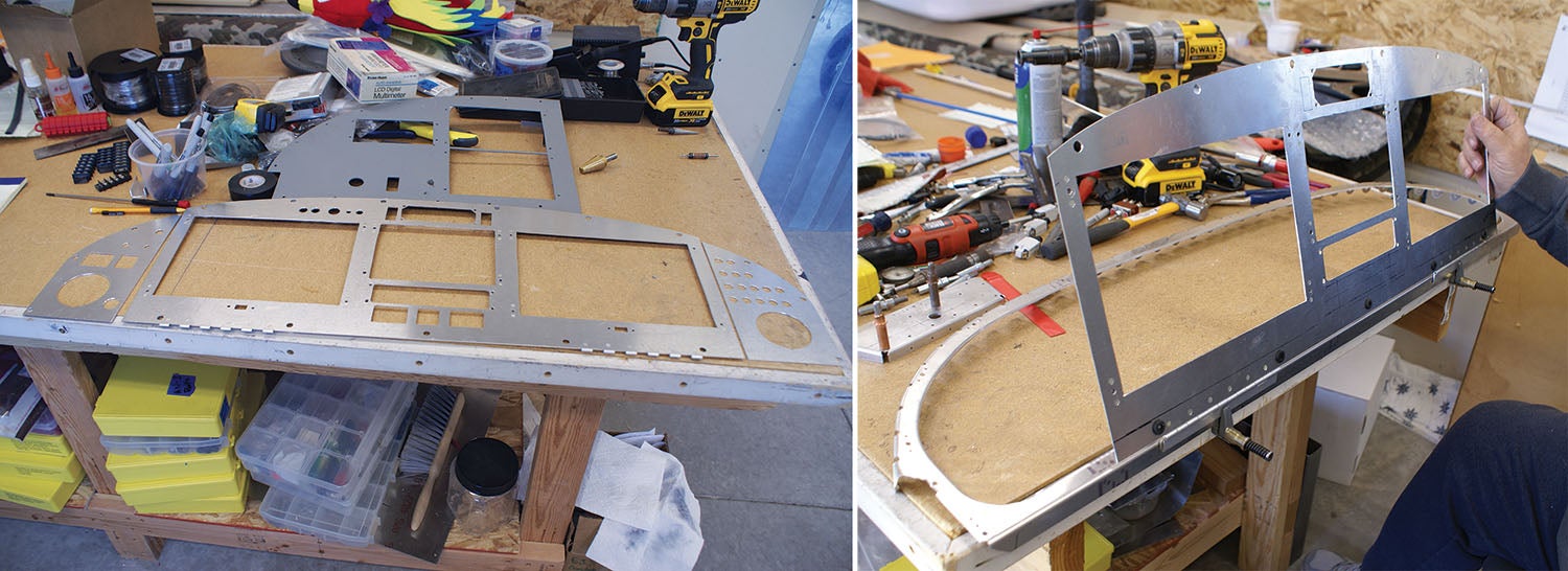
It was great to see the panel coming together with the various instruments. We would also try several fittings into the frame of the plane, just to make sure things were fitting the way we thought they would. We made a quick side trip to the Carson City airport where we heard someone had a metal shear that we could get the side-panel cuts done easily. I am so glad we decided to go this route because the cuts came out clean, straight, quick and no metal was wasted. It was the perfect tool for the job!
Once those side panels were created and riveted in, Mike showed me another fine idea he had up his sleeve, one that I really didn’t appreciate until I saw it. He added a swing-away, drop-down subpanel to the left side panel that will remain folded up during flight, because it is something that is set and largely ignored during flight. (See “Hidden Gems” below.)
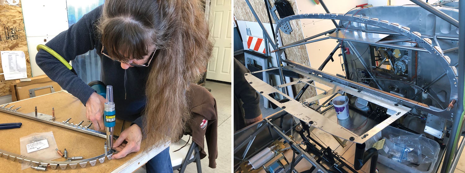
Now that the panel was completely cut out the way we wanted, it was time to consider getting it powder-coated! There’s a local place we took it to and had the job done. At this point, we don’t know the paint scheme we are going to go with, so we are sticking with gray tones for the interior because it goes with everything! Once we got it back and tried it on for size, we had the awareness that the hinges and instrument subpanel that were attached to the instrument panel frame were not powder coated and looked a “little funny,” so we found a matching color of spray paint and took care of that issue!
Another interesting idea Mike was planning all along, that I really didn’t appreciate the need for until I saw the end product finalized with all attached pieces and parts, was that he built out of some extra aluminum a shelf behind the instrument panel below the boot cowl for the many devices that are required for the function of the GRT EFISes, autopilot, voltage regulators and SDS system that are “behind the scenes” for the functionality of the system. We will go into more detail in the next article when we discuss the wiring.
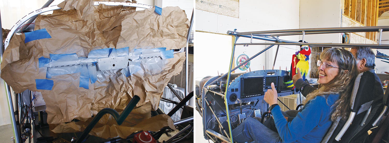
All in all, we have a beautiful instrument panel that will take care of us well into the future! When creating your instrument panel, this is the end result you want—to be satisfied with the result. I am extremely satisfied with the panel and, overall, with how the plane is shaping up. I can’t wait to fly!
![[Credit: JetStream Rider]](https://www.kitplanes.com/wp-content/uploads/2026/04/AdobeStock_345999332.jpg?w=218&h=150&crop=1 "2026 Avionics and Lights Buyer’s Guide")
![[Credit: Radiant Technology]](https://www.kitplanes.com/wp-content/uploads/2026/04/550095_5165745cc27748a598699799d796fd94mv2.jpg?w=218&h=150&crop=1 "Radiant Technology Unveils SafeGyro")
![[Credit: Dynon]](https://www.kitplanes.com/wp-content/uploads/2026/04/EMS-stand-alone_HDX.png?w=218&h=150&crop=1 "Dynon Unveils Scalable Engine Monitoring for Kitbuilders")


