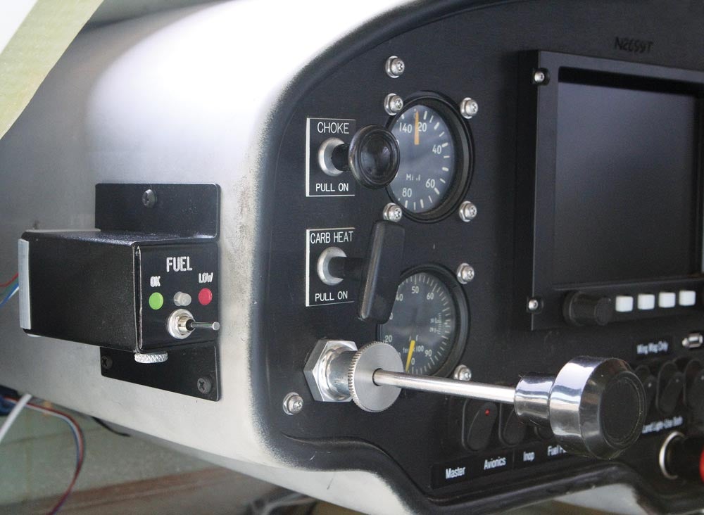
Given the compact nature of the Radiant Bingo 3 LED assembly, I figured mounting it would be a matter of finding some vacant real estate on my panel, drilling a couple of holes and—voilà—that would be the end of the story.
Obviously (since you’re reading this), that wasn’t the case. What happened was, as I was surveying the panel, every potential space came with a “hmm, that doesn’t look right.”
The problem was completely aesthetic. When Bob Fritz* designed the panel, he positioned things in such a way that, without really noticing it, it looks right. So, no matter where I thought about mounting the LED, it would mess up Bob’s carefully planned symmetry.
Ultimately, I decided on Plan B, which quickly jelled in the form of a mini subpanel that could be attached to the panel cowling. Granted, from an artistic standpoint, it would be something of a wart, but the location provided direct visibility to the LED and no installation complications. It also gave me plenty of room to use the optional 9-volt battery.
Back at the shop, I played around with various ideas. The circuit board for the Bingo 3 detector is an all-in-one device: the switch, LED and connectors for the detector, and the power supply. Since I planned to use the 9-volt battery, I would also need a convenient way to access the battery for routine replacement. As usual, a solution evolved as the project progressed.
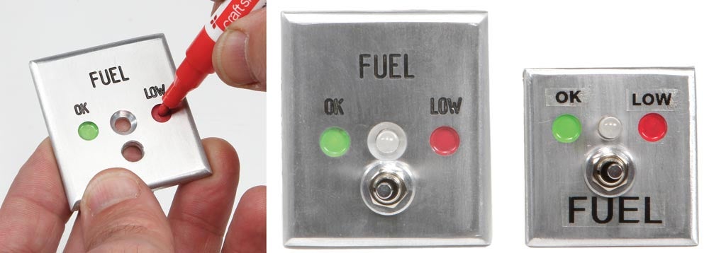
I started by making a faceplate to confirm the relative position of the LED and switch. This consisted of drilling two holes 0.384 inch apart on center. I also milled two shallow pockets for indicator dots using a ¼-inch end mill. After cleaning up the edges and fingerprints, I labeled the panel with stick-on lettering from my handy DYMO tape labeler.
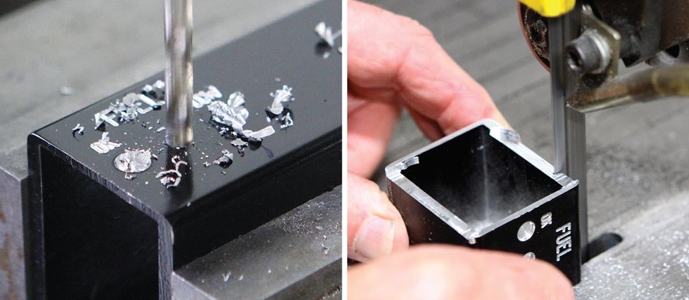
The machining stock for the panel was a section of rectangular aluminum tubing. When making small or thin parts like this, I often use square or rectangle tubing because it simplifies holding the work on the mill. It’s a lot easier (and more secure) to clamp a piece of square or rectangle tubing in a mill vise than thin plate or flexible sheet. Granted, three sides end up as waste, but the time saved more than makes up for it.
The resulting panel confirmed the position of the holes, but I realized it was too small to provide enough space for the battery. I also got to thinking the adhesive tape labels looked cheap. What I really should do, I thought, was engrave the lettering with a CNC machine.
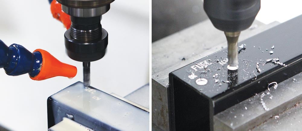
I’ve done CNC engraving in the past and it’s pretty simple: If you can draw or trace letters with lines, arcs and circles, a CNC machine can follow it. The same work-holding logic applies when machining thin parts on a CNC machine: Rectangle tubing in the mill vise simplified the setup for engraving.
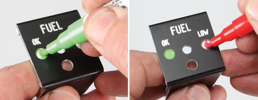
Sample panel number two looked better. I picked up a set of paint pens at my local craft store to color in the dots and “ink” the lettering.
I was happy with the contrast between the silver face and black lettering but realized, duh, that aircraft panels are never silver. They’re usually some shade of black or dark gray with a matte finish to prevent glare and annoying reflections.
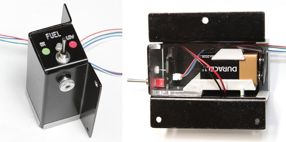
I ended up spraying a coat of semigloss black paint and then, after letting the paint dry overnight, CNC-machining (engraving) the lettering through the paint. I also took advantage of the rectangle stock to create an extension tray to provide a place to attach the battery holder and a thumbscrew to fix the panel to the sheet-metal housing.
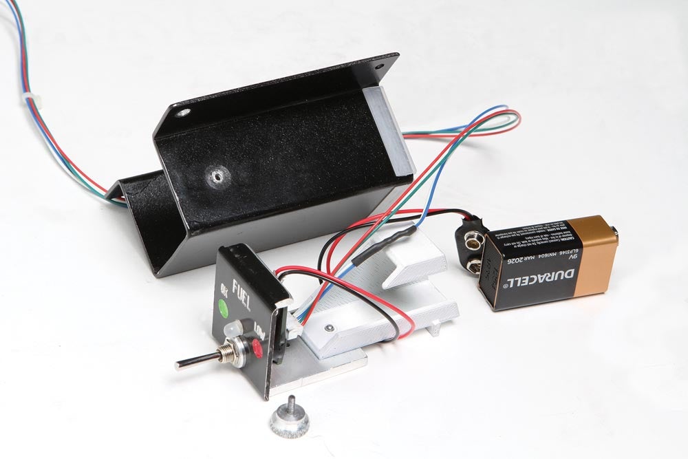
I shopped around for a suitable battery holder but eventually decided to make my own design using a 3D printer. The main feature has the battery holder riveted to the panel tray so the battery can be replaced easily.
All that was left was to cut and bend the sheet-metal enclosure (0.063-inch-thick 6061 aluminum) to hold the panel assembly and provide a way to mount my new gadget to the panel cowling.
It may seem like a lot of work for such a small project, but it really wasn’t. It took maybe 15 minutes to sketch the lettering in CAD and maybe 30 seconds to load it into FlashCut CNC software and set the parameters to generate a toolpath for CNC engraving. I spent considerably more time than that rummaging through my material supply looking for potential machining stock!
That’s it for now; time to get back in the shop and make some chips.
*Bob Fritz was the builder of Jabiru N2699T and wrote the Home Shop Machinist column for KITPLANES® until he passed away in 2011.
![[Credit: Radiant Technology]](https://www.kitplanes.com/wp-content/uploads/2026/04/550095_5165745cc27748a598699799d796fd94mv2.jpg?w=218&h=150&crop=1 "Radiant Technology Unveils SafeGyro")


![The alternative to bending down as the propeller is pulled through the compression stroke is to keep the back straight and bend the knees slightly, stepping away in a crouch. [Credit: LeRoy Cook]](https://www.kitplanes.com/wp-content/uploads/2026/05/IMG_1519-scaled.jpg?w=324&h=160&crop=1 "Manual Starting Methods")


