“I canna give ye more, Cap’n. The dilithium crystals are already overloaded.”
—Star Trek
This month’s article is more of a simple tutorial instead of a project. However, it forms the fundamental power source for nearly all of my projects. Here’s the deal: Running a circuit directly from the battery supply of an aircraft is a particularly bad idea for several reasons. Among them is that the voltage can vary from about +12 to +14 and anywhere in between. The voltage is “dirty.” That is, it can have alternator whine on it, it can instantaneously change from voltage to voltage as a function of whatever else you turn on (landing lights, landing gear, transponder, etc.), and it can pick up noise from battery cables that run hither and yon from spinner to taillight.
If you choose to follow my lead and build one of my projects and need a power supply for it, I hope this column will help you understand and modify my project to meet the requirements for your aircraft.
Back in the dark ages (when I had dark hair), we used simple Zener diodes as regulators. They were OK in their time, but we have progressed to more sophisticated devices. (Access the data sheet. You will need this data sheet to understand the notes to the images.)
Most of us use what is called a “regulator” circuit between the battery and our beloved circuits. The regulator actually performs a dual function: keeping the circuit supply voltage or current constant and also stripping off any battery bus noise. There are two configurations that a voltage regulator can have—“buck” or “boost.” The buck regulator puts out a voltage lower than the battery bus, and the boost regulator puts out a voltage higher than the battery voltage.
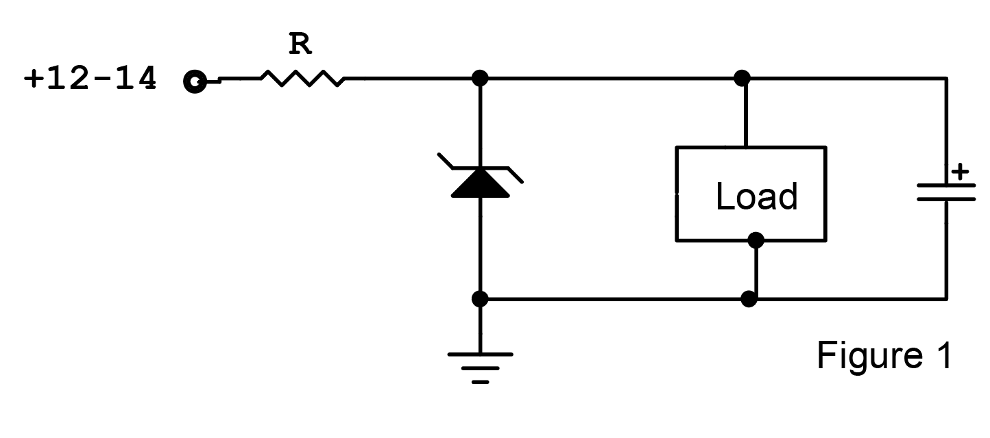
For example, the load requires 10 volts to operate, so we will use a 10-volt Zener (1N4740). The average input voltage is 13 volts (halfway between 12 and 14) and the Zener voltage is 10 volts. This gives a voltage across the resistor of 3 volts. The load current is measured at 90 milliamps (90 mA). From the data sheet, the regulator current is 91 mA. Half of this is 45 mA. Add this to the load current for a total circuit current of 135 mA.
Three volts divided by 0.135 amperes (135 mA) is 22.2 ohms. The closest standard resistor is 22 ohms. Power is I2 * R. 1352 * 22 = 0.4 watts. A 22-ohm half-watt resistor will work just fine.
Capacitor values between 10 and 100 microfarads will do away with almost all the noise in all of these circuits.
If we were to try and cover all possible combinations of voltage/current regulators and buck/boost circuits, this column would need an extra 100 pages for this month’s issue. I’ll cover a few of the more popular buck circuits, but you might want to see if your local library has a good electronics circuits section1,2 for more detailed circuits.
Most voltage regulator families have either fixed or adjustable output voltages. For example, the populator fixed 78xx series of positive voltage regulators have outputs of 5 volts (7805), 8 volts (7808), 10 volts (7810), 12 volts (7812), 15 volts (7815) and 24 volts (7824), and all have a maximum output current of 1.5 amps and a maximum operating temperature of 260° F (125°C). Both of these maximums have internal protection, and the part just shuts down rather than destroying itself. Here is a great discussion of this series of regulators.
There are a few problems with these regulators, and we have devised a whole bunch of ways around the problems since the 78 series was introduced in 1970 (50+ years ago). One of the problems is that if you want a voltage that’s not one of the six options, then you have to do some fancy footwork to convert these fixed voltage devices into a variable (but still regulated) voltage. Another problem is that the input voltage needs to be at least 2.5 volts above the output for enough “headroom” for the regulator to maintain a regulated output (i.e., for the 7810 to provide a regulated output, the input needs to be at least 12.5 volts, and the aircraft supply can’t guarantee that under all conditions). One of the problems is that the metal package of the 78 series is connected to the GND pin of the input and the metal package is used to get the heat out of the regulator.
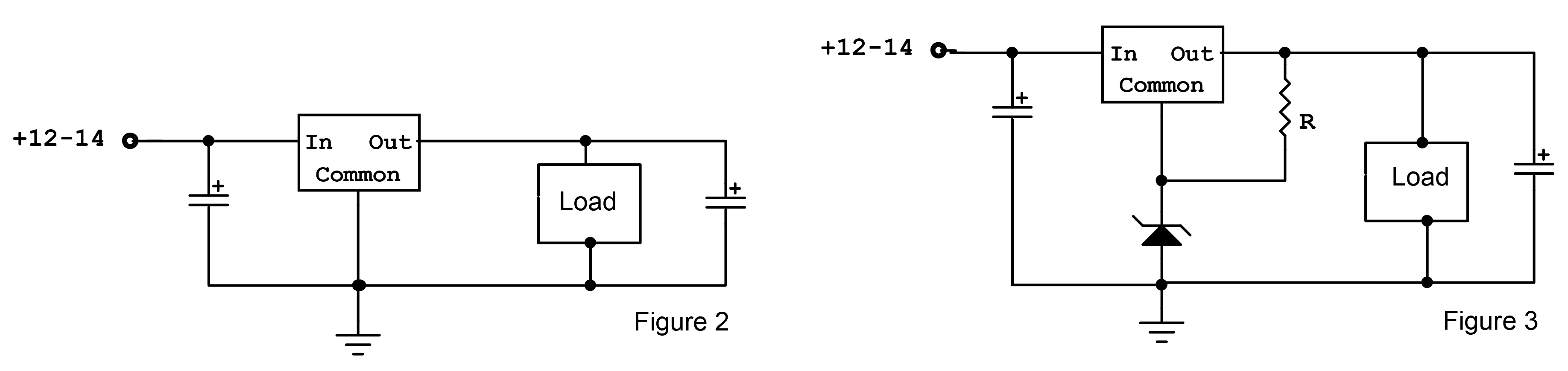
Figure 3: If you need an oddball voltage, say, 8 volts for your load, you can use a 78(L)05 5-volt regulator and “trick” the 5-volt regulator into thinking it is an 8-volt regulator by inserting a 3-volt Zener (1N4728) between “common” and ground. Actually, the “3-volt” Zener is only available in a 3.3-volt version, so the actual output voltage won’t be exactly 8 volts, but 8.3 volts. R is calculated by taking the IC output voltage (8.3) and subtracting the Zener voltage (3.3) giving 5 volts across the resistor. Running some reasonable current through the diode/resistor combination (say, for example, the “test current” of 76 mA) gives a resistor of 65.8 ohms. 68 is the closest standard value, and calculating wattage as above (0.39 watts) says a 68-ohm half-watt resistor will do just fine.
My chosen way of getting around all of these problems is a really neat device called an LD1085. The device comes in a version that is intended to be used as a variable output that is set with two resistors (1 cent each). It is an LDO (low dropout) device that needs less than 2 volts of headroom. It comes in a package that is electrically isolated from the package to the rest of the device. To boot, it has 3 amps of guaranteed output as opposed to the 78 series of 1.5 amps. The problem is that the 1085 has only one source while the 78 series has half a dozen, thus guaranteeing that one source going belly-up does not shut down the supply line.
No matter what device you use, there will be a problem called heat. That is, there is a price to pay for this regulation, and it comes with getting the regulation device hot. The equation is perfectly simple: Take the difference between battery voltage and the regulator output voltage. Multiply it by the output current, and this is the number of watts of heat you need to get rid of before the device overheats and shuts down (P = ((Vin – Vo) * Iout). Mostly we try and get rid of it by bolting the device to a hunk of metal and hoping that the metal can radiate enough of that heat into the ambient air to get rid of the heat. Me? I help the situation along with a computer CPU fan rated for the battery voltage blowing cold ambient air onto that metal plate. Reliability? I’ve had a fan on my personal computer CPU for at least 15 years 24/7 and as yet, not a single complaint from the fan bearings (131,400 hours—that’s 66 engine overhauls).
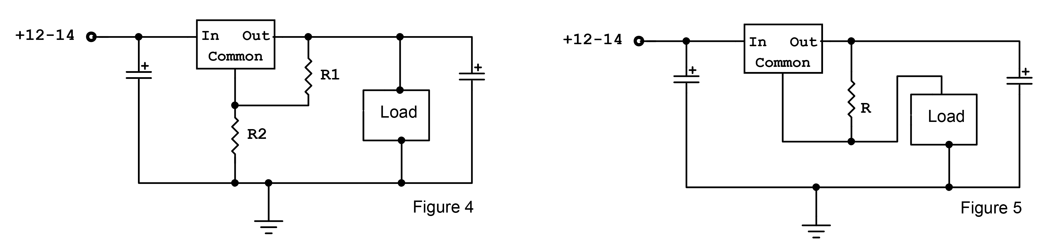
Figure 5: Every now and again (like with most LEDs), you will need a regulated current and not a regulated voltage. A simple one-resistor circuit with either the LM-317 or the LD-1085 will give you constant current. The equation is simple. The reference voltage at “common” (1.25 volts) divided by the regulated current into the load is the value of R. For example, in the landing light or rotating beacon columns in the past few issues, I used an LED that required 700 mA (0.7 amps). As I said, the reference common voltage is 1.25 volts. R is therefore 1.25 / 0.7 or 1.79 ohms. 1.8 is the closest standard value, and the wattage is I2 * R or 0.72 * 1.8 or 0.89 watts. A 1.8-ohm 2-watt resistor will work.
Suppose you are working with a low-power circuit that doesn’t need amps of current but milliamps in a much smaller package. However, you also want to have a voltage that is not supplied by the fixed outputs that the 78 high-power series provides.
One of the 78 series regulators (the 78L series) provides 100 mA of current in a tiny little TO-92 package that we can use to good advantage. The 78L series comes in the same voltage range as its larger brothers, and we can “boop” (that’s a technical term, you’ll get used to it) the 78L05’s 5 volts to power our logic or RF circuits with regulated voltage.
The problem is that the 78L05 is temperature sensitive2. The current out of the “common” terminal is very sensitive to temperature. But it is also much more sensitive to voltage at that terminal. We can also fool the 78L05 into providing an output voltage of our choice between 5 volts and within 3 volts of the aircraft battery supply to the ground terminal with a resistive divider or a Zener diode.
In an upcoming column I’ll use the 78L05 as a temperature sensor to figure out how hot your engine is really getting.
All the way to the end of this column, and I still haven’t discussed switching power supplies for higher voltages from the battery supply. Patience…all will be revealed. Until then…stay tuned.
Notes:
- “The Art Of Electronics,” Paul Horowitz and Winfield Hill, Cambridge University Press, 1993. IBSN 0-1521-37095-7
- “Foundations of Electronics,” Russell L. Meade, Delmar Publishers, 1994. ISBN 09-8273-5970-5


What I don’t understand is how battery voltage can be dirty.
Should have a very low internal resistance. Basically a big, big capacitor.
What am I missing?
“The Art of Electronics” is now in its 3rd Edition, 2015.
Comments are closed.