 Here we go again. If you’ve read my previous articles you probably already know more about fiberglass and paint than you ever wanted. Granted, I don’t know much, so the proverbial thimble filled up fast. No need to bore you with reruns.

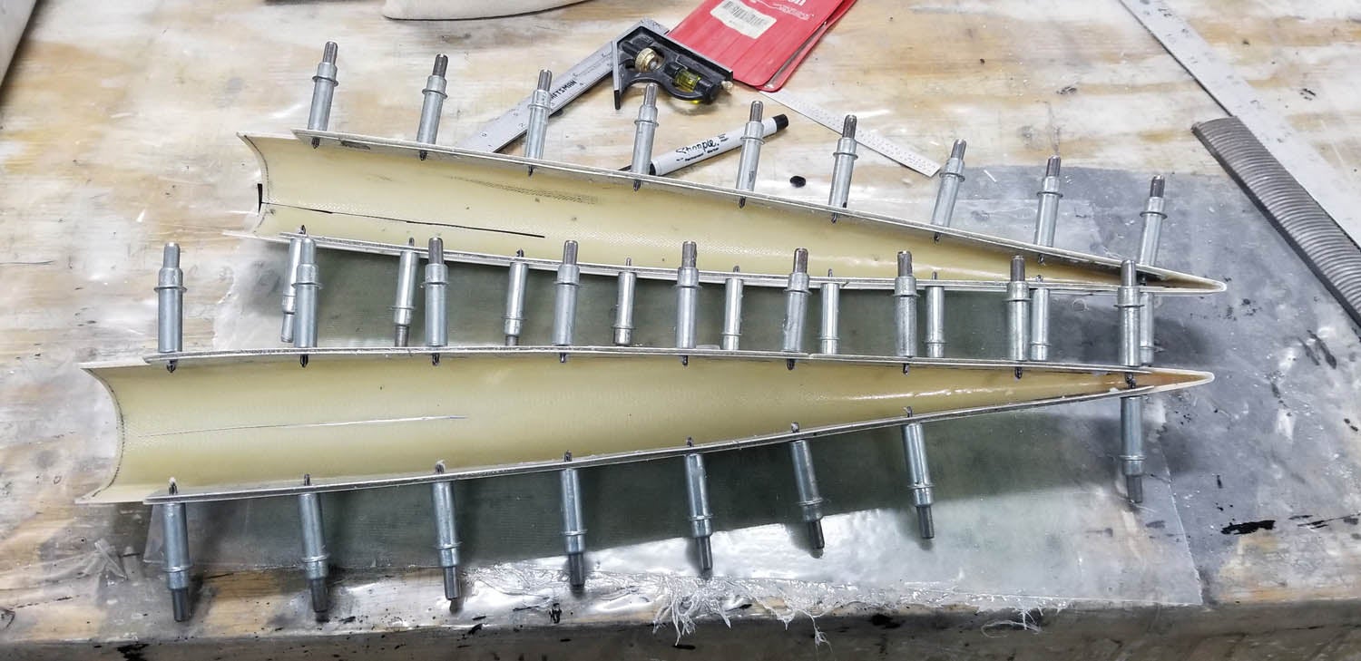
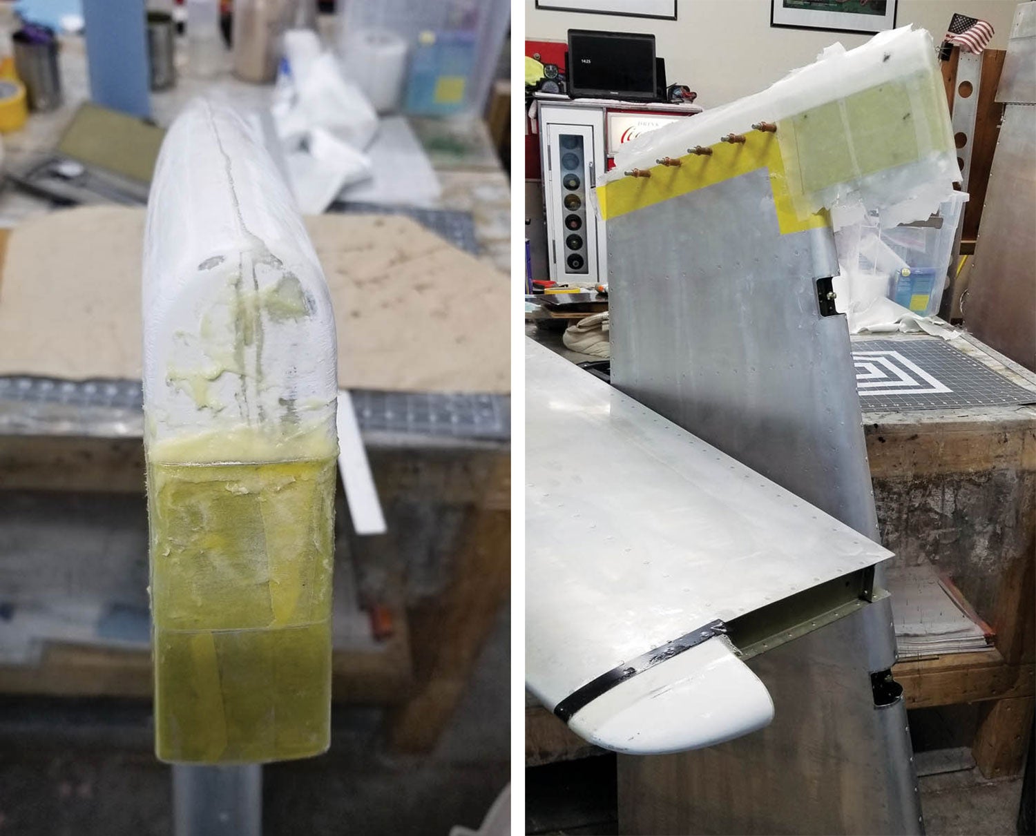
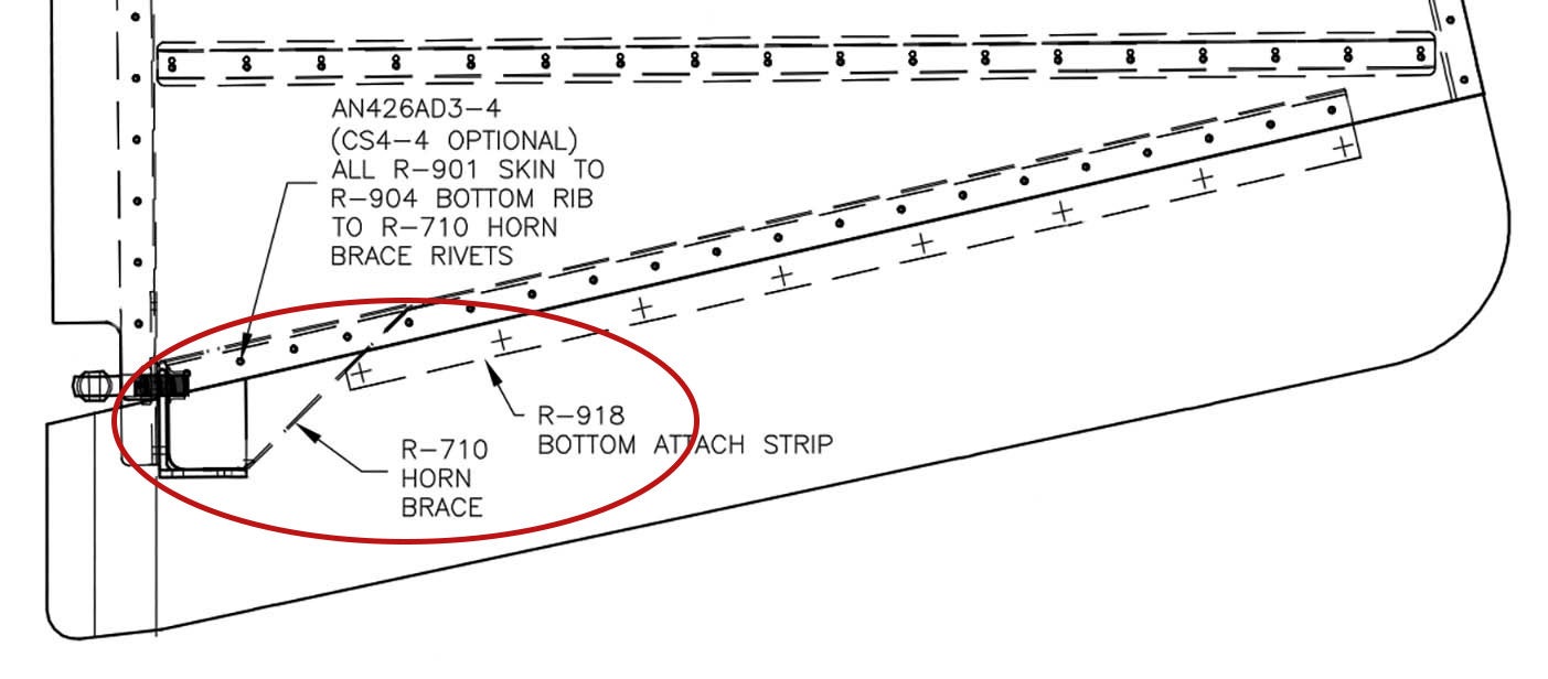
Control surface tips can be done a few different ways. Some builders simply rivet them on and leave the dressing to the paint shop. Some prefer to fiberglass the joint so the rivets and joint don’t show. I took another approach. My plan is to vinyl wrap the airplane. I wanted the tips painted because I lack the skill to do a beautiful job wrapping the curved surfaces. To that goal, I prepped them so the edges of the fiberglass were sharp up to the edges of the skin. I also did not like the look of the joggle on the elevators and rudder. See the elevator drawing area circled in red the photo. The rudder has one as well. I glassed that area so it wouldn’t show. So, here are some tip tips applicable to all three solutions.
Supplies
Remember that 12×12-inch four-ply layup we made while practicing for the canopy skirt? Dig that thing out. It’s really useful here. If not, lay up four plies between two sheets of 4-mil plastic and squeegee it flat.
Find a chunk of pink closed-cell construction foam. Look for a construction site and ask for a piece. No need to buy a 4×8-foot sheet. It should be safe for epoxy but just in case, mix a tiny bit and apply it to a test piece. Closed-cell foam is preferred because it doesn’t absorb water into the foam core.

Fit the Tips
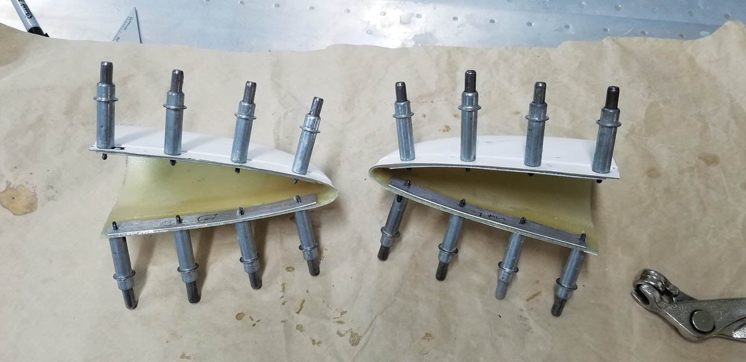
Elevator tips are pretty straightforward because the counterweight is encapsulated and all that’s needed is a basic cap. Horizontal and vertical stabilizer tips are a little different. The following procedure works for both. The rudder bottom tip is also different. It has its own procedure left for last.
First, check the fit. They’ve been sitting on a shelf, hopefully standing on edge. No doubt they deformed a little. The better they fit, the less work you have to do. Slip one on. If it’s tight, that’s OK. If it falls in, we need to spread it a little. Heat it with a hair dryer or heat gun until it’s almost too hot to handle, but no hotter than 200° F. Slide it over the outside of the control surface. Yes, outside. Leave it until it cools. We want it to retain enough shape so it fits with outward pressure. Repeat with both elevator tips and horizontal stabilizer tips. Next file the edges as needed so they fit. Most parts have a little extra flange and it bottoms out before the part fits flush. Once the tips fit, move on to trimming.
Slide the elevator tip into place, making sure it’s firmly into the trailing edge point. There should be a little extra on the forward end. You need room for the cap (~1/16 inch). Trim off the rest nice and square to the forward end of the counterweight.
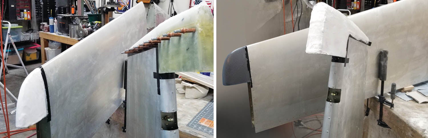
Adjust the Heim joints per the plans. Mount the control surface(s). Let’s concentrate on the elevator and horizontal stabilizer. Take a straightedge and extend the forward face of the control surface tip as a line from the edge. It’s a reference line. That’s the finished dimension of the elevator tip and counterbalance arm. Now figure out how much gap you want. I chose 1/8 inch. Remember, paint will decrease the gap at least a few thousandths, plus the weight needs room to clear as it swings. Measure from the reference line and use a square to draw a line using the outboard edge of the horizontal stabilizer as a reference. Theoretically it should be parallel to the line previously drawn. If not, you should check why it’s not. Either way these are your reference lines to cut the horizontal stabilizer tip and, if necessary, trim the skin.
Remove the control surface. Trim the skin if needed. Install the horizontal stabilizer tip and extend the cut line onto the fiberglass tip. You want the cut parallel to the forward edge of the control surface or it will look weird. Cut, reinstall and double-check before moving on to closing the cap.
Add Caps
The forward end of the elevator counterweight arm is solid, so all we do is cover the end by bonding a cap in place. The horizontal and vertical stabilizer tips are cavities and need a little structure. A technique from my RC aircraft days works great: foam ribs.

Sand the mating surfaces of the tip caps with 80-grit and clean with solvent. Clean the insides as well. They are pretty rough already. Cleco the tips in place.
Remember that 12×12-inch layup? It works great for tip caps. Trace the shape of the elevator tip on the previously fabricated flat layup. The counterweight arm can be covered with fiberglass later. Repeat with the horizontal stabilizer tips. Cut the tip caps and sand to fit just inside the edge of the tip or cap. Rough up both sides and label them so you can get each back in the correct orientation and in the correct tip or cap. Trace the horizontal stabilizer tip caps on a section of closed-cell foam about a half-inch thick. Cut and sand the plugs so each fits inside the tip. I prefer the cap inside because as the tip is sanded, there’s almost no way to sand past the cap and flox. Label them. These are horizontal stabilizer tip ribs. Use some epoxy to bond the foam ribs into place about one-eighth inch shy of the tip edge, leaving room for the tip cap later. Cure while Clecoed in place so the tip doesn’t change shape.
Apply some neat epoxy inside, then a single layer of glass to the interior exposed side. West Systems 105 is fine here. Mix some epoxy and apply it neatly to the exposed foam and the tip cap. Mix in some flox and bond the tip cap in place using flox to fill any gaps. The tip cap fits into the recess. Excess should squeegee itself out.
The foam core rib will provide strength to the tip and cap. Minor weight gain for a lot of structure.
Bonding and Riveting the Tips
Fabricate two strips of the thinnest aluminum in the scrap bin. Match drill and bond them to the inside of the caps for additional structure for the rivets. Strips of carbon fiber also work very well. I prefer floxed G-Flex epoxy to bond them, then set aside to cure.

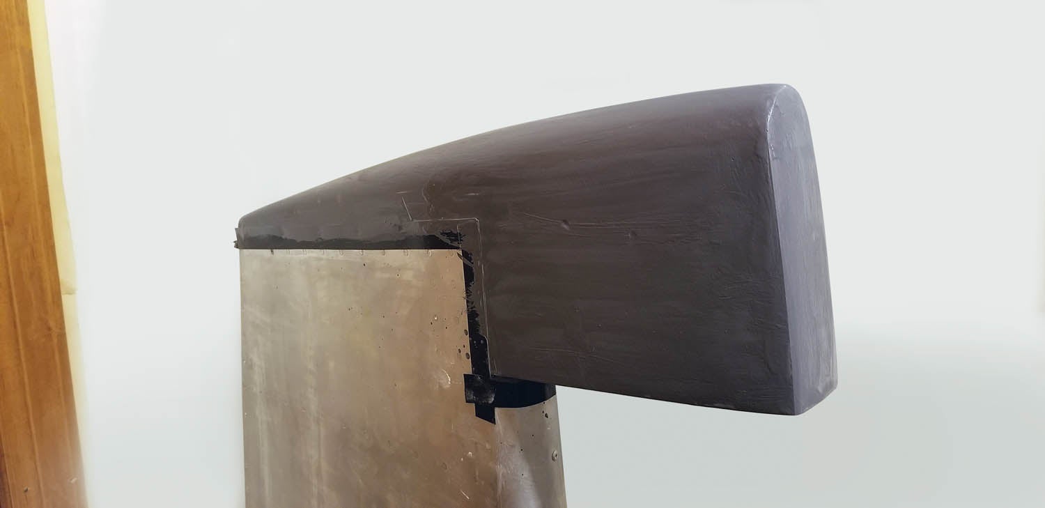
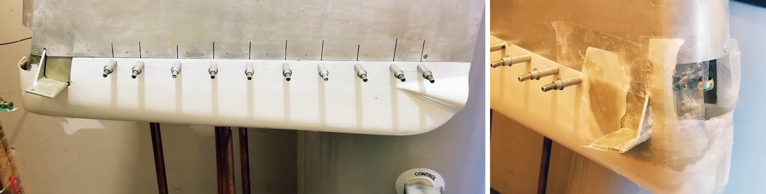
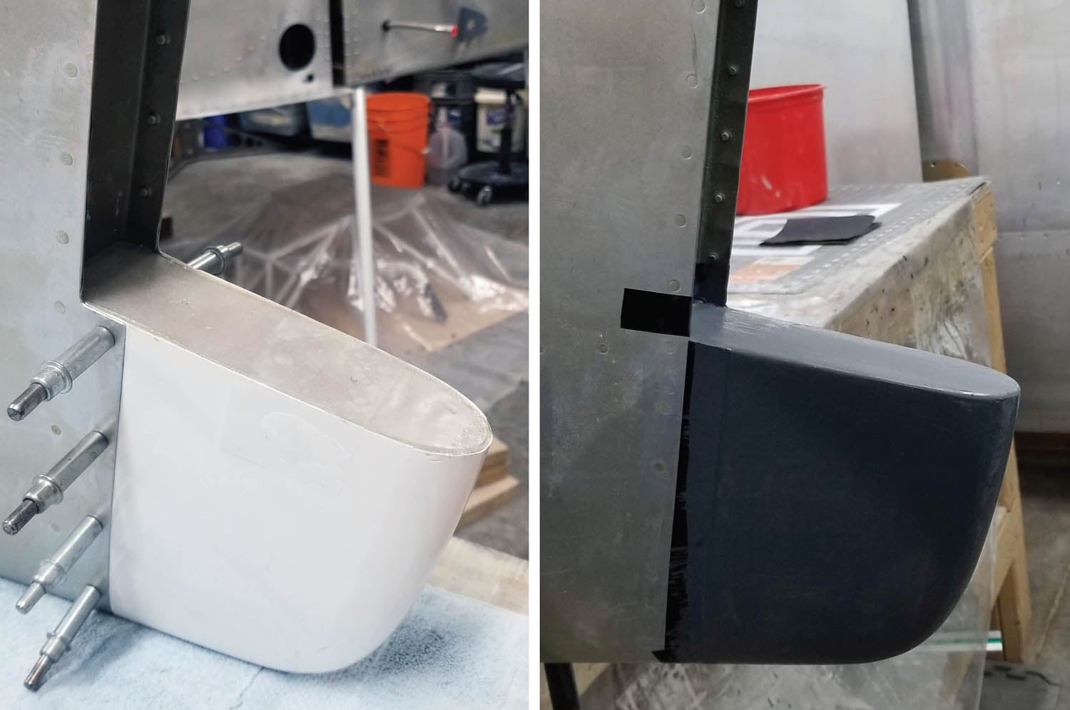
Final drill and countersink as required. Prep the tip for final assembly. Rough up mating surfaces of the tip and skin. Make sure it fits and the mating edge is even to the skin. Sand or fill as needed. It’s much easier to do this work before the tip is permanent. Tape off the skin with black electrical tape to make sure it doesn’t get damaged. Test fit the elevators to the horizontal stabilizer and make sure they move freely. It’s easier to fix now than after everything is bonded and riveted in place.
Now is the time to give serious consideration to the counterbalance joggle, seams and rivets. Proceed with attaching tips and caps. I prefer West Systems G-Flex epoxy to bond the tips and caps before riveting. The stronger bond reduces the potential for paint cracking from vibration and stress. Tape off the skin to the edge with packing tape. Wipe it with wax. Sand and clean the mating surfaces. Spread a thin layer of G-Flex epoxy neatly before mixing in a little flox. Mix it to a thin toothpaste consistency and apply to mating surfaces, then assemble with Clecoes. Wipe off the excess and fully cure before final riveting. Rivet per the plans.

Filling the Elevator and Rudder Counterbalance Joggles
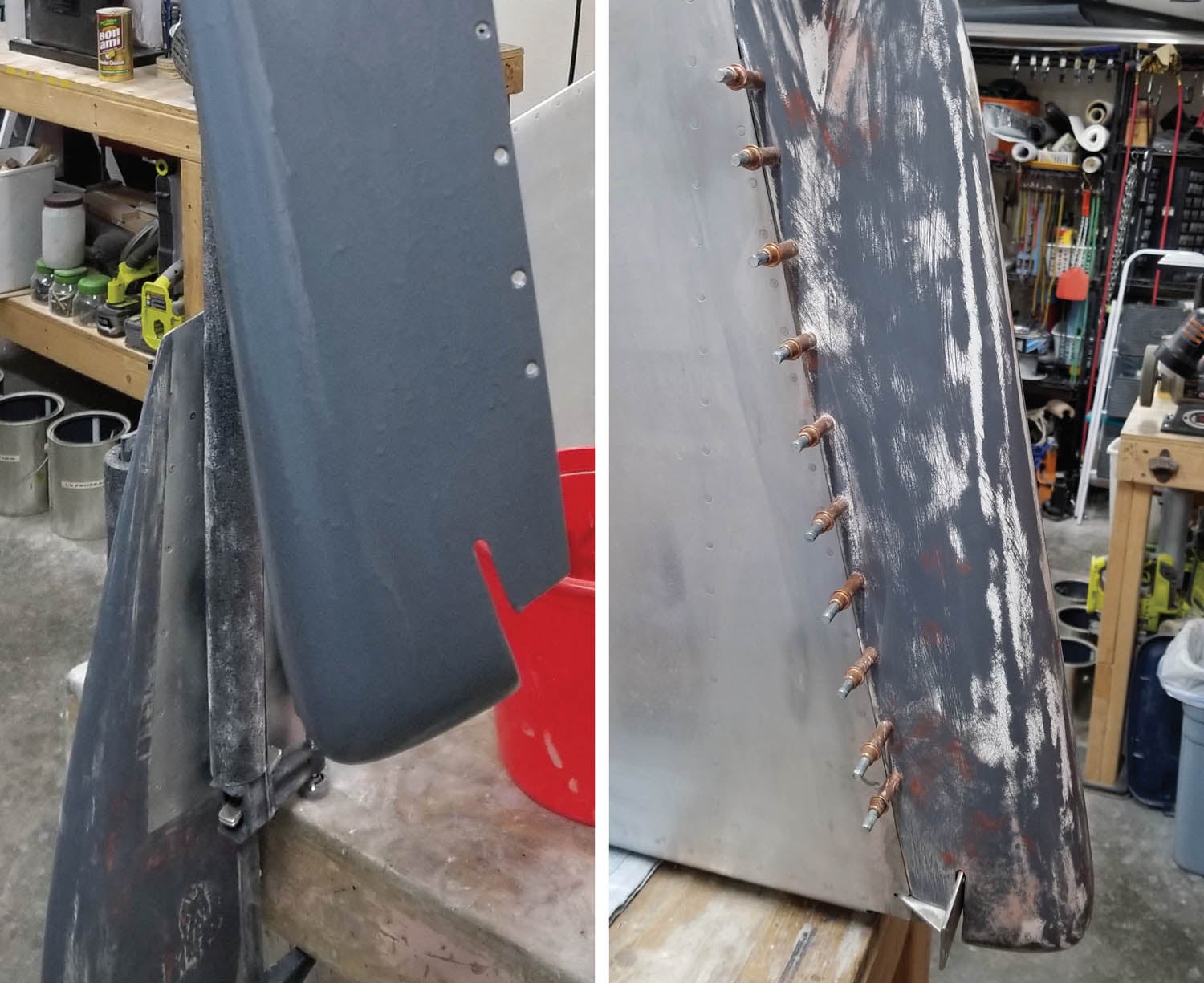
If you want to cover the joggles and/or the seams, it gets a little more complicated. Filling the joggle is easy: Tape off anything you don’t want covered in epoxy. I taped right up to the skin edge. Mask everything else. Trust me—epoxy gets everywhere. Calculate the area and thickness needed up to the seam. We need to fill the joggle area up to the level of the skin and tip. It should be about 0.032 inch. That’s about three layers. I actually did this before the tip was bonded. I covered areas with heavy packing tape and applied a layup to cover the area. Basically, I made the cap bigger so it covered the joggle areas. After it cured, the cap was popped off, and it was finished. It’s a bit more work but a lot less sanding on the control surface. If you go this route, don’t bond or rivet the tip until this step is done. It’s easy to fill the pop rivets with micro and make it look really nice.
Rough up the area with 80-grit. If you’re using my technique, wax the heavy packing tape so the tip can be removed. Mix some epoxy neatly. Apply the three-layer fiberglass layup to the joggle up to the seam. Cut another piece of cloth slightly bigger to overlap the seam and tip and apply it as well. If it extends past the aluminum edges of the counterbalance arm, that can be filed off later. Peel ply and squeegee. Cure. Pop off the tip. Prep as below. Bond it with G-Flex. Remember, the new fiberglass area needs to be bonded to the joggle area as well. Proceed with paint prep.
If you want to cover the seam and rivets, apply a tape line about one inch away from the rivet line. You may want to use a lighter cloth for bridging the seams to make for a smoother scarf transition onto the aluminum. Apply peel ply and cure. Proceed with prep, but be extra careful sanding the scarf line on the skin. Don’t compromise the skin by sanding it too much. Move on to the rudder bottom tip.
Rudder Bottom
Ugh. The rudder bottom. Oh, bother. Maybe this will help someone. After fighting with it for quite some time, I completely changed Van’s method. Most follow Van’s instructions and trim the rudder horn area so the cap fits from below. Mine has a slot for the rudder horn and slides on from aft. The only difference is the area around the rudder horn is filled on mine. If it slides on from below, there is an exposed square. Some builders bond a small piece of fiberglass in that area to blend it in. Refer to the drawing below. The area circled in red didn’t fit very well. It wouldn’t sit flush and bowed out when Clecoed. If yours has a similar problem, remove the area that won’t fit flush and sand a scarf. A scarf joint is an area thinned from the cut back about one inch. Tape off the areas on the rudder where new fiberglass will be applied. Wax the tape. Apply new fiberglass, feathering the layers so the scarf blends and the edge is the same thickness as the rest of the bottom. Apply peel ply and cure. Pop the bottom off. Apply a layer of fiberglass over the scarf joint on the inside to further reinforce.
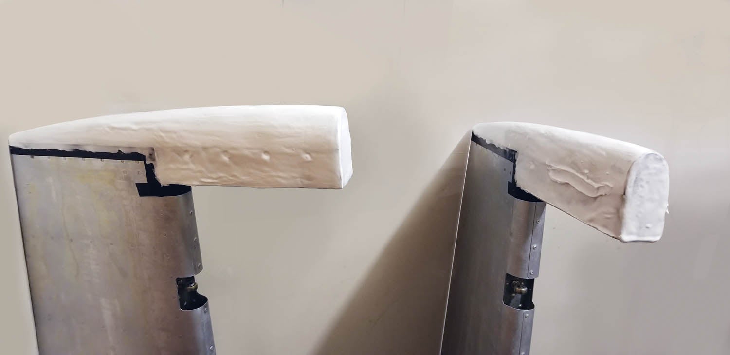
I added a foam rib at the forward lip to fill the area and bonded a fiberglass cap in place. Same procedure as above. One layer of fiberglass was applied to the inside of the foam rib. The result was a much nicer fit. It’s basically sealed right up to the rudder spar.
The rudder bottom is designed to be removed. Use nut plates and screws or pop rivets. Either will work. It only comes off occasionally. However, we still need to address the pathway and mount for the beacon. I bonded a piece of Van’s conduit to the bottom to make fishing the wire a little easier. A piece of waxed lashing string preinstalled works very well to pull the wire later.
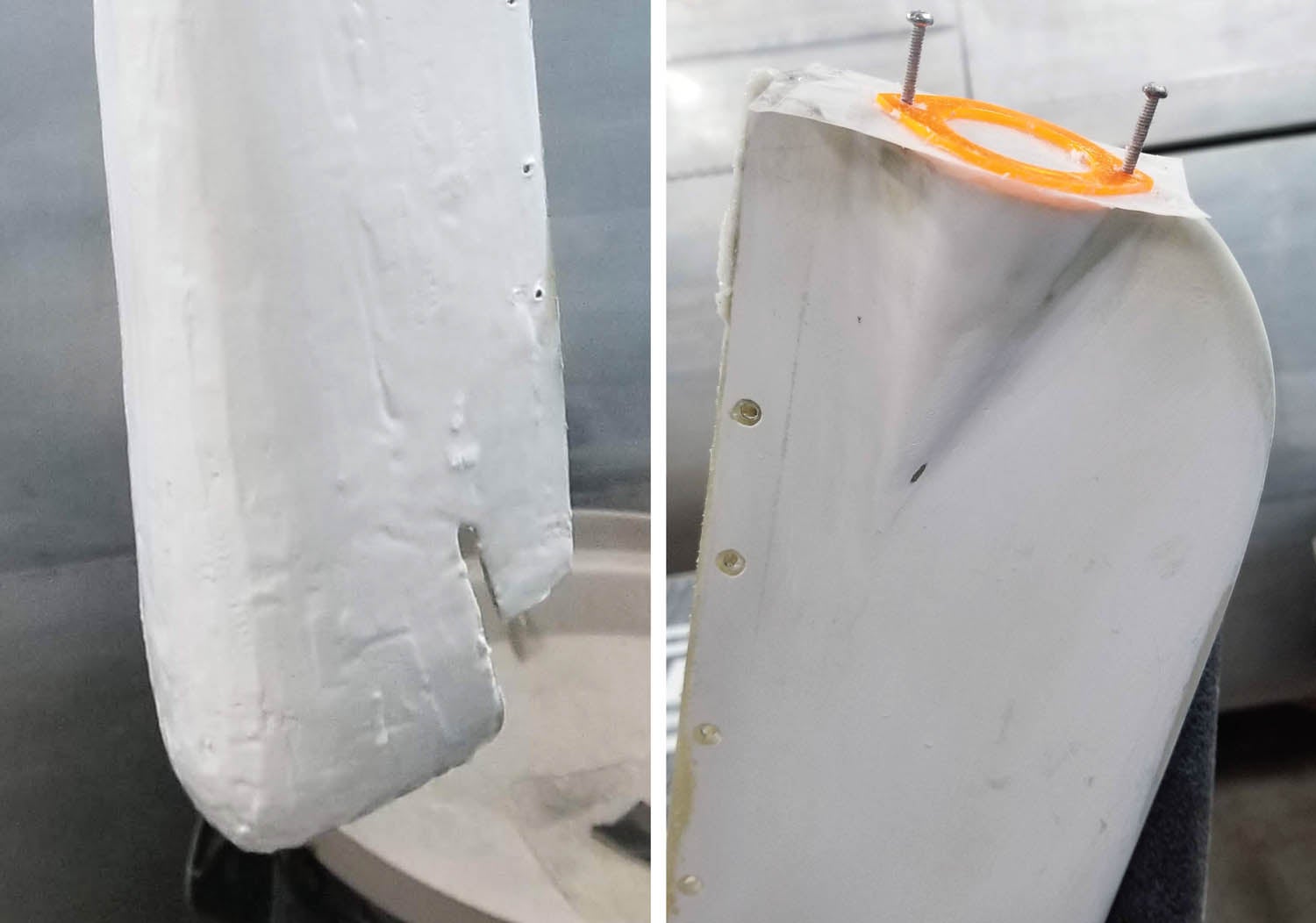
The beacon is easy. Most use the same spacing and screw (4-40) dimension. Cleaveland Aircraft Tool sells a flange you can install. Mine stripped immediately. The 4-40 holes in aluminum are really delicate. Maybe you’ll have better luck.
There’s an easier way. First make a template matching the beacon with holes. Buy several long 4-40 screws and two nuts. Use the template to drill the holes and relieve the hole area for the beacon. Wax the screws and the template. Run the screw through the template and into the holes and thread a nut on each one. Snug it down finger tight so the nuts won’t move. Mix some floxed epoxy and apply enough to encapsulate the nuts. Cure. Remove the screws. Hopefully you waxed them well and they just come right out. Run a tap through the holes to clean them up. Reinstall a fresh pair of waxed screws anytime something is applied to the beacon area so the holes don’t get accidentally filled. That’s about it. The rest is the same. Prep, prime and paint. Before installing the rudder bottom, slide a section of waxed lashing string through. A hole and snap bushing can be drilled after paint, and the wire fished through the snap bushing.
Remember to drill a weep hole in the lowest point of the rudder bottom after final rigging.
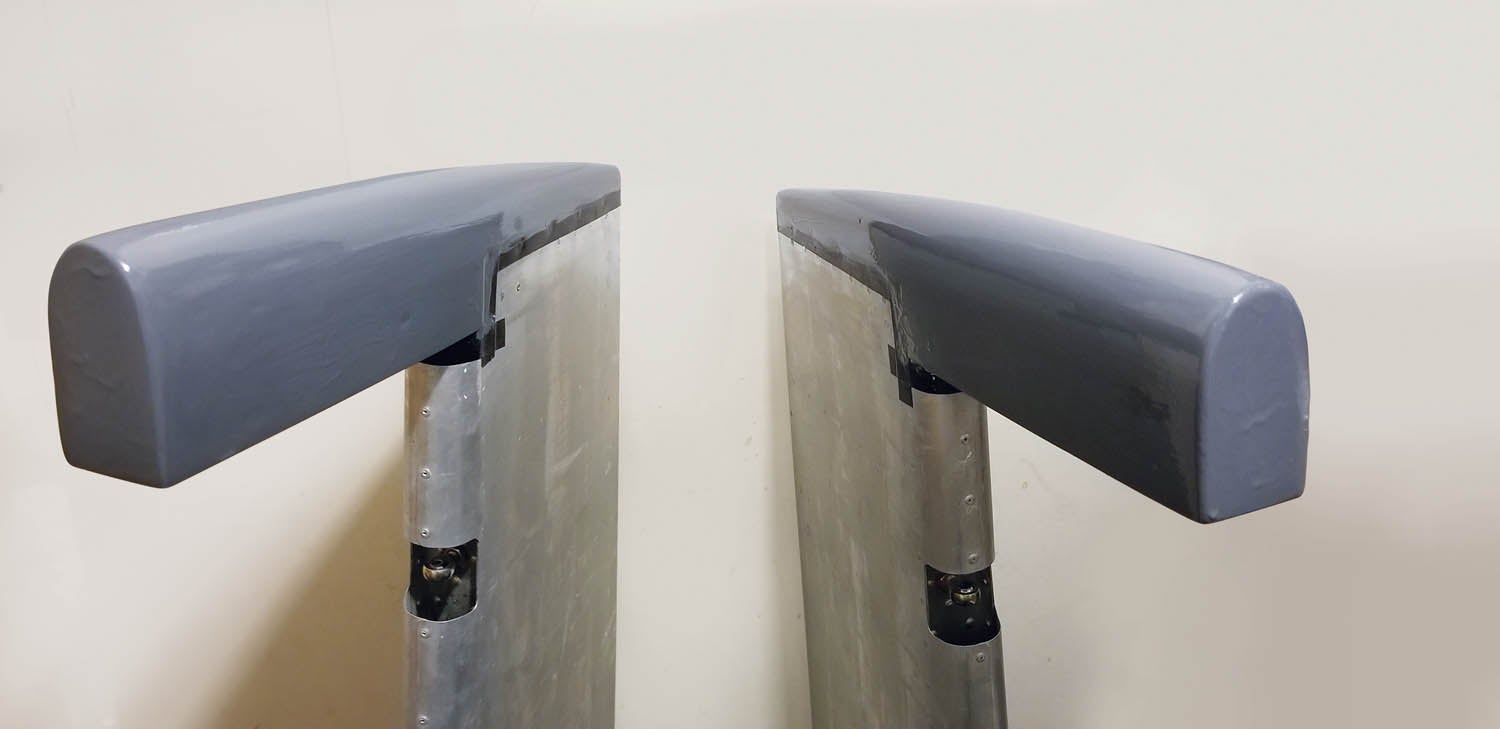
Final Prep
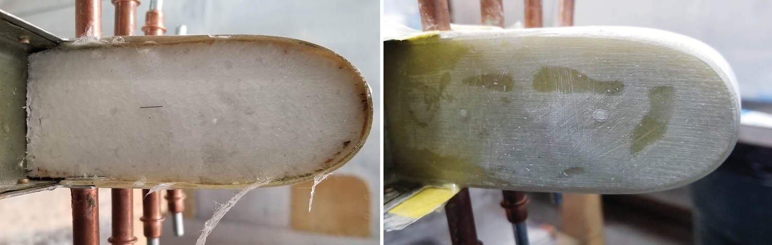
File the edges of the tips even to the counterbalance arm. Block sand. A neat trick is to mount the control surface and lock it in trail. Apply micro to the two tips and allow to cure. Sand them as a unit so the shape is consistent. Follow up with the prep and paint process described in “Easy Slider: Part 2 and Part 3.”
Thanks for tuning in. I’ll see ya when I see ya.


Oh the fiberglass fun.
Not that bad when you get into the ZEN of it.
Nice article.
Thanks Bruce. I enjoyed it. Plus, mistakes are easily repaired. Build on.
Comments are closed.