
We can do all sorts of electronic wizardry with our newfangled glass cockpits, glass airframes and glass all around, but one thing we haven’t been able to get away from is an invention straight out of the 16th century: wire to connect point A to point B.
There are as many ways to measure copper wire as there are countries that use it. American Wire Gauge, Brown and Sharpe, Birmingham and Stubbs, and those are only the ones still using the English system of measurement (feet, pounds). There are quite a few more for those fortunate folks who have converted to the metric system.
What I hope you will do is print the Copper Wire Table that accompanies this article and put it in your toolbox or hang it on your wall so that it will be handy when somebody asks, What wire size are we using? (Note that the tables are good for both solid and stranded copper wire.)
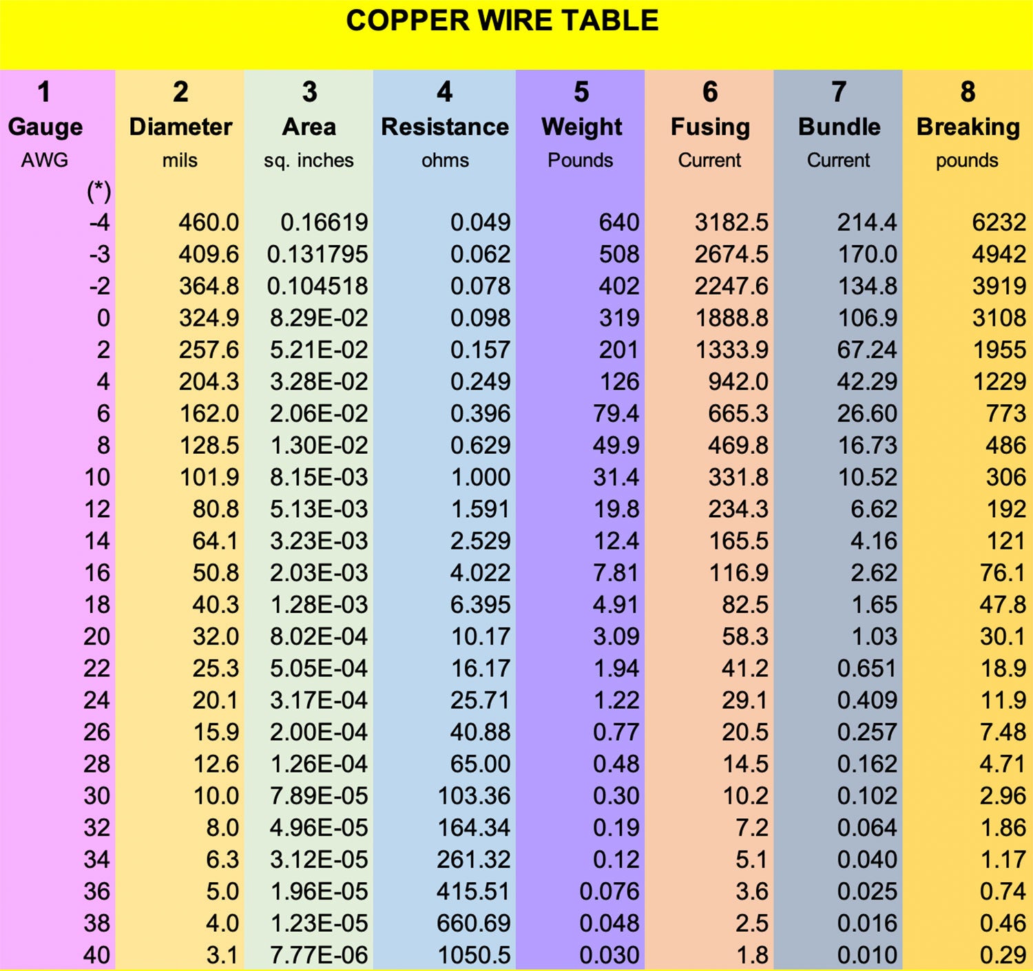
Column 1. Let’s take it a column at a time, starting with column 1 on the left. Here we see wire sizes from 0000 (commonly called four-ought and written 4/0)-which doesn’t melt until you run more than 3000 amperes through it to #40-and is approximately the diameter of the hair of a small yak (not to be confused with #38, the size of the hair of a large yak).
This is commonly called the American Wire Gauge size and has been in wide use since the Civil War. In England it is called the Brown and Sharpe Gauge and is, for all intents and purposes, the same thing. How do the sizes relate to one another? We define 4/0 to be 460 thousandths of an inch in diameter. There’s nothing magic about that size, but we had to start somewhere. Each succeeding wire size is reduced in size by a factor of 1.123. For you math nerds out there, the exact number is the 39th root of 92, which on your calculator can be programmed to be 92^(1/39).
There are a couple of interesting rules of thumb that we can deduce from this math wizardry:
A reduction of 10 gauge sizes (e.g., from #24 to #14) reduces the wire resistance by a factor of 10 and increases the weight by a factor of 10.
A reduction of six gauge sizes (e.g., from #22 to #16) increases the diameter of the wire by a factor of two.
Column 2 is the diameter of solid copper in thousandths of an inch. Stranded will, in general, be about 10% to 15% thicker. This is where the factor of 1.123 comes into play. Each diameter is 1.123 smaller as you progress from size to size down the table. (Actual value is 1.122932 to six decimal places.)
Column 3 is the area of the wire in square inches. Since somebody a long time ago found that the area of a circle is π r2, this column simply takes the value in column 2, divides it by 2000 (by 1000 because Column 2 is in thousandths of an inch and 2 because radius is half the diameter), squares this number and multiplies the result by π. Thats the beauty of a spreadsheet, by the way. You do the equation once, do it again on your calculator to make sure you are right, and then simply copy the cell all the way down the column. Real easy once you get the first equation right.
This column presentation needs a little explanation. We are dealing with small areas here, all the way from about 0.166 square inches (166 square milliinches) down to a microscopic 8 microinches (thats 0.000008 square inches). While we could probably spend the time and space to expand the column into inches, it is just as easy once you know that the notation E-3 means milli and E-6 means micro. You can convert (for example) the area of #18 wire as 1.3 square milliinches or 0.0013 square inches
Column 4 is the resistance of a 1000-foot length of the wire. To get the length of 1 foot (or 1 inch), simply divide by 1000 (or 12,000).
Column 5 is the weight of a 1000-foot length of bare wire. To estimate the weight of aircraft-quality insulated wire, add approximately 25% to the bare wire weight.
Column 6 is the amount of current (in amperes) at which the wire will melt. Note that this is only an approximation and does not take into account ambient temperature and proximity to other heat sources.
Column 7 is the one that needs a little real-world manipulation. The FAA says, for example, that #20 wire will handle currents in a bundle up to an ampere, but real-world tests show that this is off by a factor of up to four. That is, if all the other wires in the bundle are relatively cool (i.e., well below their bundle current), then #20 has been shown in experimental data to safely handle up to 4 amps. As a matter of fact, with a lot of serious digging and some fancy math, I calculated that a #20 wire at 4 amps in a bundle will have a temperature rise of less than 10 F. (See notation below for a spreadsheet calculator.)
Column 8 simply says how many fishing weights you can hang from a wire before it breaks.
Now, for the true devotee of this sort of stuff, this same wire table has been posted to my web site, www.rstengineering.com, in the Jim’s Engineering Page area, along with the real-time spreadsheet calculation of wire size versus length versus current that gives resistance, voltage drop and (most important) a real calculation of how hot the wire will get above ambient temperature. Use it with my blessing.
Ill hop back on some real electronic stuff next month. Until then, stay tuned.


