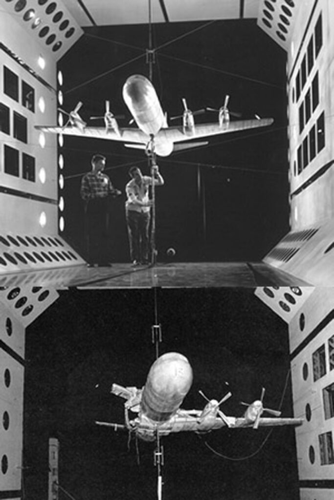
![Aircraft control surface designs may include counterweights to offset and eliminate flutter. The counterweights should not be eliminated to save weight. [Credit: Kitplanes Archive]](https://www.kitplanes.com/wp-content/uploads/2026/03/kitfox-s7-sti-04-1024x682.jpg)
Last month I made a reference to weight being The Enemy of aircraft, and for the most part that is true. I also mentioned the potential for a forward cg condition if, for instance, a heavier engine or prop is installed on the standard engine mount, necessitating additional weight in the tail. A particular anathema to most aerospace engineers is the idea of having to put a lump of lead in the tail as ballast. That is weight that you are lugging around that doesn’t contribute anything useful; if weight is needed aft, better that it be a battery, tools, a quart of oil, or even a jug of emergency water, just something that isn’t dead weight.
So I applaud anyone who, in the words of the late Colin Chapman wants to “Simplify, then add lightness.” But there are places where weight is needed and should not be deleted.
Back when I first began reading this publication around thirty years ago, there were (according to my admittedly questionable memory) a number of incidences with Kitfox aircraft builders omitting the flaperon counterweights due to said builders not seeing the point of all that weight being added. Again, I applaud their weight conscientiousness, but those bits of weight are important in that application. Why?
You’ve probably seen a sports team flag on one of those little window-mount flag poles. As the car goes down the road, that flag is flapping back and forth rapidly. That is a form of flutter, and completely undesirable for a control surface.
Picture a typical aileron that is basically triangular in cross section; its natural center of gravity is going to be roughly 1/3 of the way back from the thick forward edge. Its center of pressure is going to be somewhere closer to halfway from the leading edge base to the trailing edge. This means the forces of gravity and air pressure are fighting it out well aft of the aileron hinge, and as the aileron flaps back and forth rapidly, it can easily get into state of flutter if there is enough airspeed.
The onset of flutter is usually quite rapid (as in a matter of seconds, and even in a fraction of a second in extreme cases), and one of the scarier parts of flight test. Flutter testing usually involves “sneaking up” on flutter by increasing the airspeed in tiny (like one or two knot) increments until the flutter begins to manifest itself, and then backing off the throttle. The onset of flutter ranges from feeling an increasing vibration, to the sudden, catastrophic flutter incidences that have cost the lives of pilots.
So what does the previously mentioned weight do?
By counter balancing the control surface, the center of gravity of the combined assembly moves forward toward the hinge line. The aileron will now be much more flutter resistant as the up-down forces are being resolved at or near the hinge instead of in the middle of the aileron. This does make the assumption that the wing itself is rigid enough that there is no (or effectively no) wing flex or twist, which in itself can contribute to flutter.
A 100% balanced aileron or flaperon will be neither nose-high nor nose-down if disconnected and at rest on its hinge (assuming one of the frictionless hinges so prevalent in engineering classes). An under-balanced aileron will be tail-down, and you can figure out what over-balanced is. All of which I mention to say that an aileron does not necessarily have to be 100% balanced, it simply needs to be balanced enough to forestall the onset of flutter below Vne. Also keep in mind that your Vne may itself be a function of anticipated flutter speeds. Of note is that it may be that a control surface is only 75% balanced because that is enough to ward off flutter, and no need to add more weight than absolutely necessary. It all depends upon the control surface and its expected flight regime. If for example, an airplane is drag limited to 120 mph, then the control surface needs to be good only to that speed, plus a bit of safety margin. Again, no need to add weight that isn’t needed.
Go search for photos of a P-38 and you can see the elevator counterweights protruding from the middle of the tail plane, or a de Havilland DH.88 Comet with its rudder counterweight sticking out in front of the rudder. Why? Because balancing the control surface is a tradeoff between a short control arm with more weight, or less weight and a longer control arm. In the case of the P-38 and Comet, the aerodynamic drag of the exposed weights was an acceptable trade-off in packaging and less weight. For the same reason, our various homebuilt designs employ a mix of internal and external counterweights.
A shorter control arm typically allows for embedding the counterweight inside the wing or empennage structure and keeping it out of the airflow. However, this does require a very dense material for the counterweight in order to keep it as small as possible. What to use? Typically lead on our homebuilt aircraft, but often depleted uranium (DU) on large commercial airliners and cargo planes. Why DU? To allow a short moment arm and keep the counterweight tucked out of sight and out of the airflow. For what it’s worth, those DU counterweights are encapsulated in a thick paint and stenciled with explicit instructions not to grind or machine; it may be depleted, but you still would not want to breathe that dust!
Another way to reduce the amount of counterweight needed is to decrease the weight of the control surfaces themselves. It was quite a surprise to a much younger me to see WW II aircraft with fabric covered ailerons, rudders, and elevators! Why fabric? To minimize weight vs all-metal construction, and in turn reduce the amount of counterbalancing needed.
A slight exception to this would be on my Thorp T-18: the plans call for the ailerons constructed from 0.016-inch thick aluminum, but many of us have fabricated our aileron skins from 0.020 just for ease of construction and just a touch more heft. That 0.016-inch thickness is adequate, but is extremely flimsy to handle, and the extra 0.004-inch of aluminum contributes approximately 6/10th of an ounce to the weight of each aileron, which is in the noise in terms of balancing them.
As a side note, some builders, including myself, increased there T-18 wing skin thickness from 0.025 to 0.032, in which case that extra seven thousandths of an inch adds about 12.5 pounds to the weight of the wings, assuming I did my numbers correctly. A few comments here: being on the wing itself, that 12.5 pounds isn’t going to change the cg, just the overall weight, so no cg concerns, plus that 12.5 pounds was/is an acceptable trade-off for mitigating issues with some minor skin buckling (if I am remembering correctly), and lastly it is a well-worn path in the Thorp community, going back to when we had paper newsletters that were used to document and communicate build knowledge. In other words, I wasn’t breaking any new ground on my own. Nor did I or any other builders (that I know of) increase skin thicknesses over the rest of the aircraft, which would have then added a non-trivial amount of weight to the airframe.
That said, there have been builders who upsized thicknesses all over whatever they were building, in the name of thinking they were making it stronger or stouter, and wound up with an overweight aircraft. Don’t do that; the designer will have (should have) done the stress analysis to ensure that the specified material is strong enough for the anticipated loads. Casually exceeding the drawing specs typically just adds unneeded weight. For that matter, any modification to the designer’s plans should be approached with caution and only with approval from the designer, or with proper stress analysis and/or review by someone knowledgeable.In the case of the Kitfox counterweights, they were there for a reason, and a quick call to the factory support line would have confirmed that. Again, approach all non-cosmetic modifications with caution.
![Careful planning and determination will get you to your goal of building and flying your own airplane. [Credit: AdobeStock]](https://www.kitplanes.com/wp-content/uploads/2026/05/Pulsar-Sunset.jpg?w=218&h=150&crop=1 "Last Bits")
![Making rare use of my drafting tools for the internal timing. [All Images Credited to Andrew Robinson]](https://www.kitplanes.com/wp-content/uploads/2026/05/P1010535.jpg?w=218&h=150&crop=1 "Conquering the Magneto, Part 2")
![[Credit: AdobeStock]](https://www.kitplanes.com/wp-content/uploads/2026/05/AdobeStock_262642207_AGCuesta.jpg?w=218&h=150&crop=1 "Winging It")
![Lowell Farrand spent years serving as an FAA DAR and is in the EAA Hall of Fame. He offers sound advise to builders. [Credit: Bill Wilson]](https://www.kitplanes.com/wp-content/uploads/2026/05/unnamed-4.jpg?w=218&h=150&crop=1 "Think Like a Builder")
![Humberd and his daughter using the 701 for some farm duty transportation. [All Images Credited to Jon Humberd]](https://www.kitplanes.com/wp-content/uploads/2026/05/1-3.jpg?w=218&h=150&crop=1 "Builder’s Spotlight")
![[Credit: Viking Aircraft Engines]](https://www.kitplanes.com/wp-content/uploads/2026/04/engine.jpg?w=218&h=150&crop=1 "Editor’s Log")
![Author Bill Wilson takes a break from measuring and cutting the Lexan windshield during his Onex build. [All Images Credit to Bill Wilson]](https://www.kitplanes.com/wp-content/uploads/2026/04/image-2.jpg?w=218&h=150&crop=1 "Think Like A Builder")
![Andrew bought a Thorp T-18 project, which started him down the road to experimental aircraft project ownership and construction. [Credit: Andrew Robinson]](https://www.kitplanes.com/wp-content/uploads/2026/04/IMG_7725-scaled.jpeg?w=218&h=150&crop=1 "Winging It")
![The integrated ECLIPSE NG features a very sunlight readable display that shows the engine and all flight data organized in one or more pages. [Credit: Fielden Aero LLC]](https://www.kitplanes.com/wp-content/uploads/2026/04/1_Screenshot_.jpg?w=218&h=150&crop=1 "FLYBOX Avionics")


Thank you for an excellent article on flutter.
I have a link to an awesome 1 min flutter illustration off of YouTube I can send you.
https://drive.google.com/file/d/1BsCpCyz02HeByLv7HnvMgIp0TiLU7jCu/view?usp=drive_link
It is a German video using a weight to illustrate the importance of balanced controls with the weight forward of the hinge point.
Comments are closed.