We are headed into airshow calendar time. I don’t care if it is the granddaddy of them all (Oshkosh) or the usual four beat-up Airknockers and Scarecoups flying into Podunk Intentional for cold pancakes and greasy bacon, we all bring our handhelds to listen to the comings and goings on the aircraft band.
We have several ways of putting a signal into/from that handheld. One of the two portable ways is very portable, for such things as airport advisory stations (Unicom) out in the field to help inform traffic like a Unicom should, but located where the operator can visually see what is going on out on the ramp or in the parking lot.
The two portable types are the ground plane and vertical dipole. I’ll show you how do both of them. They will be constructed with plain old copper wire taken from surplus house-wiring (Romex) cable. We will be doing all this with BNC connectors. For those of you with OSM/SMA small threaded connectors, I’ll give you a source for BNC/SMA adapters.
I did a library search for the number of times I’ve told you about dipoles or ground planes. From the time I started writing for KITPLANES® (October 1985 issue, 37 years ago), I’ve mentioned ground planes and/or dipoles 68 times. I’ve specifically given information for construction of one or both of them eight times.
This is the first time I’ve given instructions on the nuts-and-bolts construction details of both of them in one article. While I’ve been pretty scarce on matching coaxial cable to antennas, I’ll go into significant detail on this matching.
Because I’ve talked a great deal over the last 30+ years about the concept of wavelength, I’ll give a few formulas for its calculation, but I will not go into infinite detail about radar, squirrels, and British plumbing standards (see “Three to Get Ready,” September 2018).
As an example, I’m going to use the popular CTAF (Unicom) frequency 122.8 MHz, which is pretty much the center of the CTAF frequencies (122.700, 122.725, 122.800, 122.975, 123.000, 123.050, 123.075 MHz). Don’t worry about precision; there is less than ¼ inch variation from one end of the band to the other and therefore less than 1/8 inch no matter where you go in the band. If you’ve got some other goofy frequency to use, then use the formula.
Given that caveat, the formula for wavelength in inches is
wavelength = 11,800 / frequency (in Mhz)
and therefore a full wavelength at 122.8 is 96.1 inches. A quarter wavelength is therefore 24.1 inches. Almost. Using the wire size we are going to use yields a “foreshortening effect” of 5% or so; therefore the elements should be 22.8 inches. About. (See the “tuning” discussion below.)
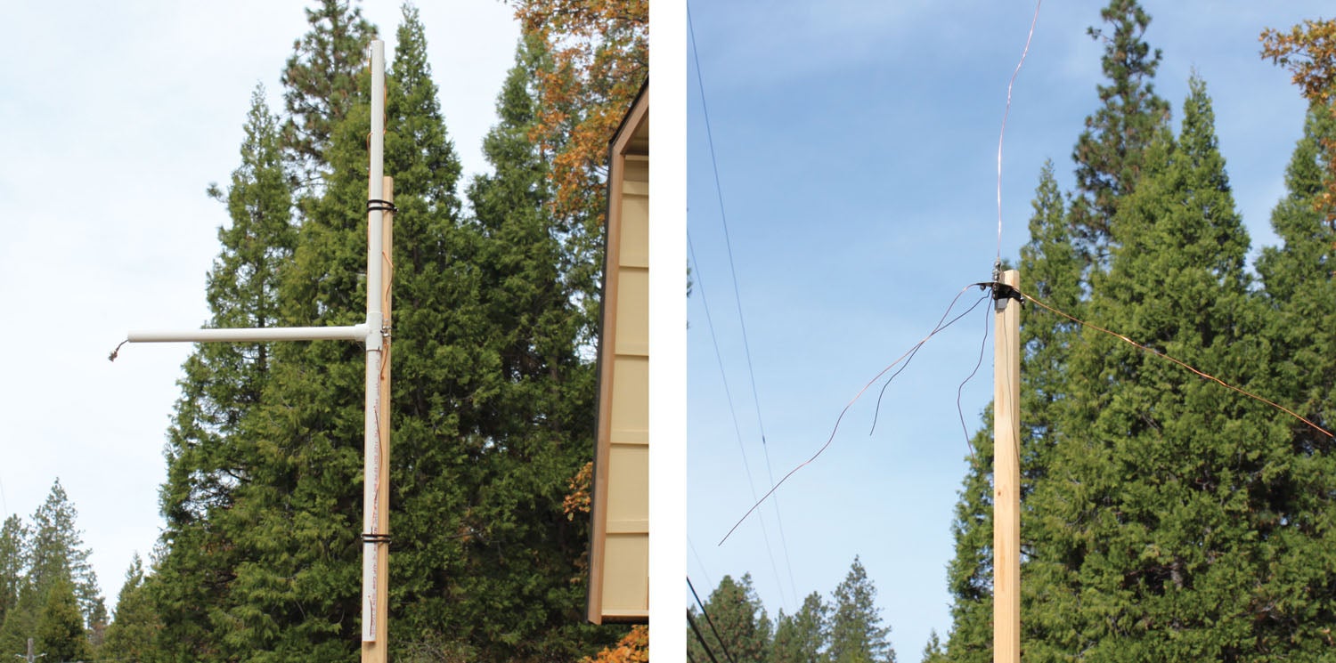
Vertical Dipole
The vertical dipole is a fairly easy version of the two antenna variants to make, but not quite as easy to make as the ground plane. The heart of the antenna (the radiating elements) is going to be made out of #14 copper wire, the kind that comes to us in the form of house wiring…three elements per length of Romex house wire. And we only need two of them. The hardest part of making this antenna is to strip both black and white wires to get the copper wire inside of them. (Keep the bare ground wire; we are going to use it in the ground plane.)
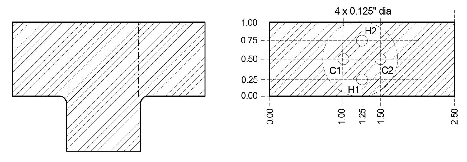
Cut three 24-inch pieces of 1/2-inch PVC water pipe. Drill A PVC 1/2-inch tee fitting as shown. Stand by—here comes the magic.
Back in 1957, when I was just a wee lad of 13, an engineer from the FCC labs in Laurel, Maryland, developed a really inexpensive balun (rhymes with Alan and gallon). In his honor we generally call it a Roberts balun, but Collins Radio used it a lot, and some call it the Collins balun. It consists solely of a single piece of coaxial cable. That’s it. No trick circuits or magic beans. Just coax.
What I told you above about how to calculate a quarter wavelength was accurate. Almost. That was for a quarter wave in air. A quarter wave in coax has a factor due to the coax polyethylene insulator between the center conductor and outer braid shield. Polyethylene has a “velocity factor” of 0.66. That is, a quarter wave in air at 122.8 MHz is 24 inches, as we said above. However, in a coax cable, that wavelength has been slowed down by a factor of 0.66, so a quarter wave is only 16 inches. Think about it: When you run on a track, you can probably do 15 seconds or so for the 100-meter dash. Now, how fast do you think you can do it up to your neck in the swimming pool?
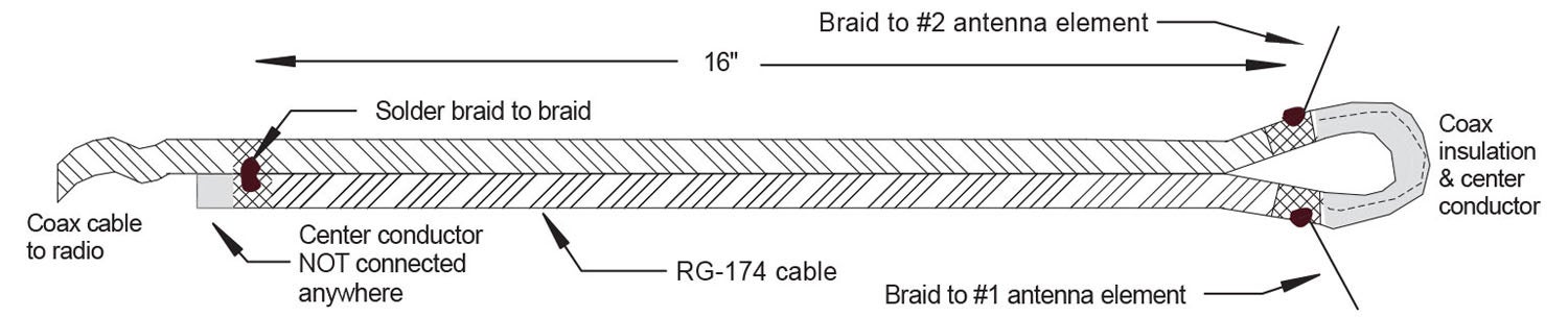
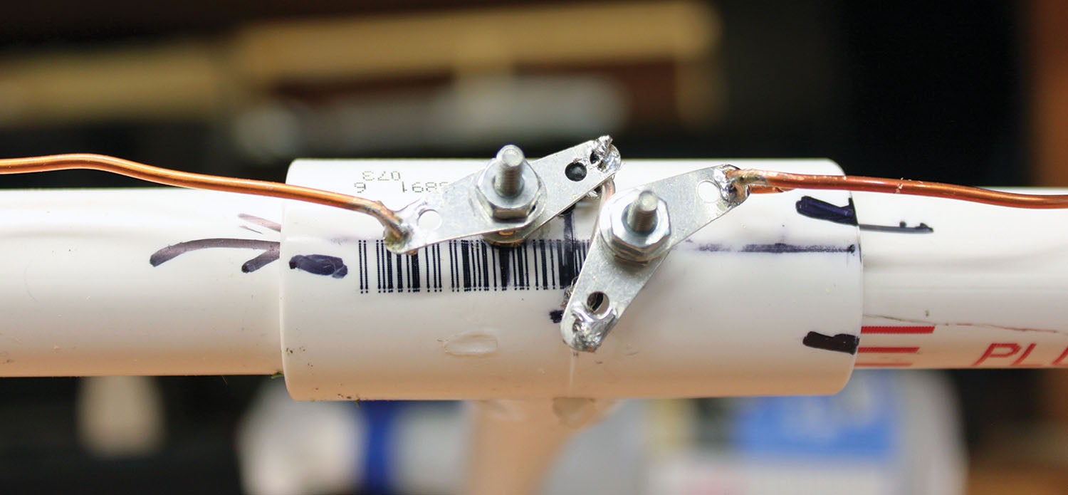
The Roberts balun is nothing more than a quarter wavelength of coax braid connected to the antenna at one end and to itself at the other end (the center conductor connects nowhere at the antenna end). It feeds the BALanced “ears” of the dipole from UNbalanced coaxial cable. Simple in the extreme. The only trick, if there is one, is to strip the outer black jacket of the coax without cutting the inside braid. A plain old multifunction hand crimper with stripping jaws works just fine.
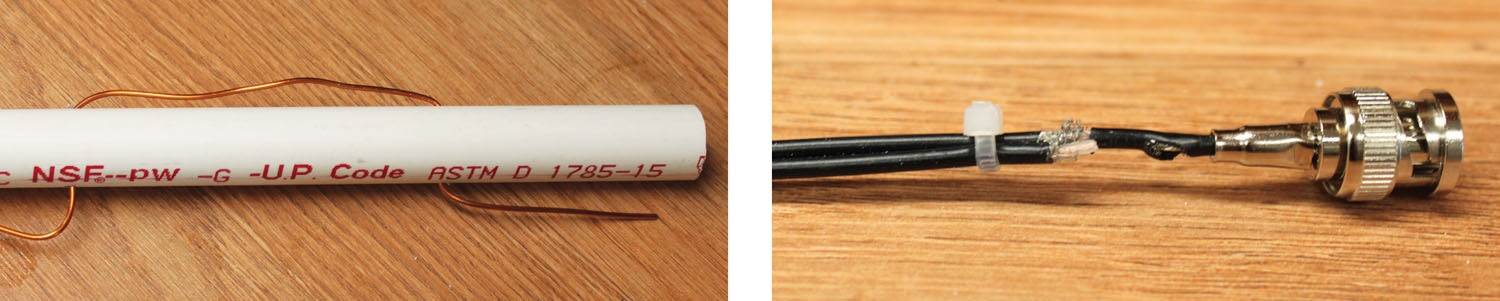
As shown, one of the braid sections is connected to each end of the dipole wires, and the bottom end of the quarter wave section is connected back to the main coax with bare wire (cut off resistor ends?). If you are really careful, you can solder them braid to braid without any wire.
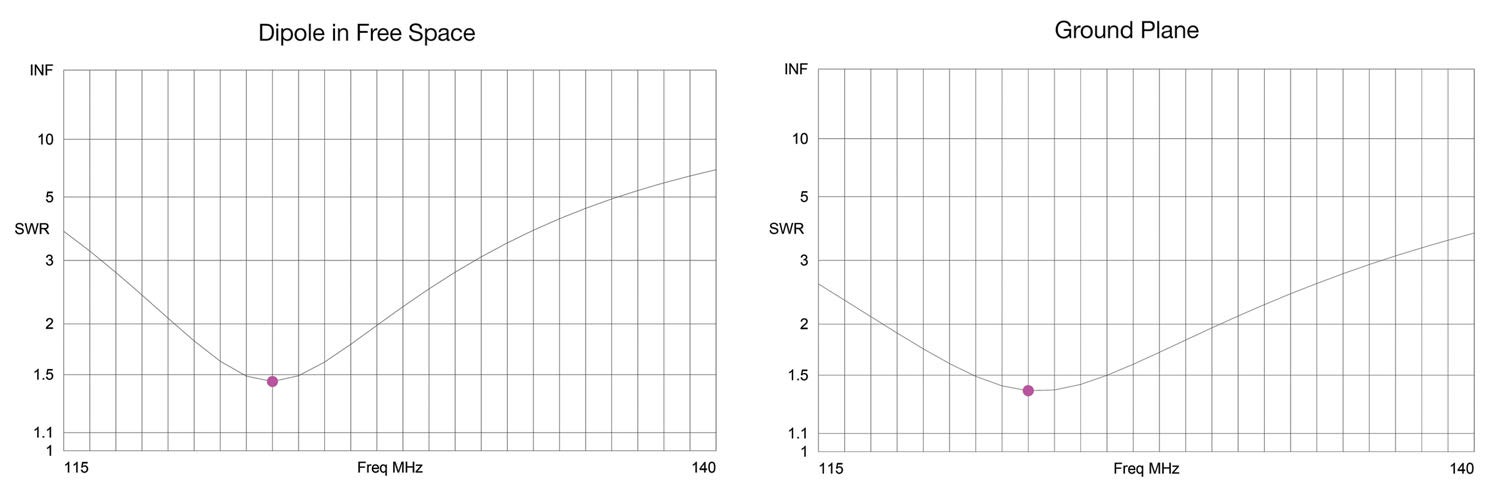
Now to wind up the dipole design. Use that antenna structure to do a VSWR check if you have the instrumentation. Use the multipurpose antenna tuning tool as shown to minimize VSWR on your chosen frequency. Use the tuning principle my old daddy taught me—start to clip off just a little bit more than you think will make it perfect and don’t take it. Even better, tune the antenna to 122.0 and when you clip off just a little too much and the VSWR goes up, you should have hit 122.8 on the nose.
I purposely didn’t give you step-by-step instructions, but good photos and drawings illustrate a Weirfer that I’ve adopted for my last 40 years of college teaching for a reason—decent instructions are almost impossible without figures. Do this: A visitor from the planet Jimfer has landed, speaks English and noticed you have your shoes laced up with a knot at the top. Without demonstrations, drawings or photographs, words alone on paper can’t tell a visitor how to tie that knot. It is nearly impossible.
Ground Plane
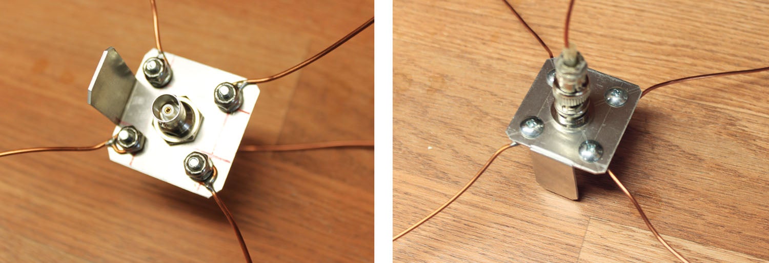
The ground plane is pretty obvious without a whole lot of words. The four ground plane elements are true quarter wave elements (without any shortening), and the center element is a quarter wave shortened with the 95% formula shown for the dipole. There are some things to remember:
• The ground plane elements (radials) are measured from the center of the center BNC connector, not the edge of the mounting plate.
• The mounting plate can be as large or as small as you wish. Just remember that the mounting plate becomes a part of the ground plane.
• The BNC bulkhead connector shown in the photos is an inexpensive UG-260. There are two versions of this connector. One is the regular old 260. The other one is the weatherproof UG-260, which is a lot more expensive and totally unnecessary in this application.
• If you wish, for mechanical reasons, you may leave all of the copper elements (four ground plane wires plus a radiating wire) inside of their plastic Romex insulation. It will not affect the operation of the antenna in the least.
One thing you should know during the construction: The center impedance of a quarter wave whip above a ground plane like this is about 32 ohms. The center impedance of a dipole like this is about 72 ohms. Without a matching balun, you are trying to match the 32 ohms of the whip to a 50-ohm coaxial cable. However, if you bend the ground radials down, you are starting to make a dipole antenna. At some point, that 32 ohms will begin to rise from 32 to go to a dipole at 72 ohms. Somewhere in between (at about a 45° angle) those radials will hit the magic 50 ohms and be a perfect match. The balun on the dipole does that auto-magically, but you can do it mechanically with a ground plane.
You would be best advised to use BNC connectors on this pair of antennas. BNC connectors are available from nearly every source, even (believe it or not) Walmart. The SMA connector on most popular handhelds will need an adapter to convert the SMA to BNC, but even that is widely available from the same sources. Google “RF connector adapter BNC to TNC,” and you will have a few dozen sources to pick from.
Enough of antennas, already. In the coming months I may go retro on a few of the old favorites I’ve written about in years past, including the backyard wind direction “wood airplane on a stick” variety, but with upgrades to charge the internal lithium-ion cells with solar power and stuff like that. Until then…stay tuned…


s")


The information is good but what you failed to mention is that when you go through the process of requesting a Unicom frequency for the airport, you have to specify where that antenna is going to be installed and at what height. You also have to specify the amount of portables and mobile radios. If you install that antenna and you connect it to a portable, or you move your Unicom base to use that antenna, you’re opening yourself up for an FCC violation and possible sanctions up to losing your license.
That may be the legality of it, but it is rarely, if ever, enforced. In my 55 years of working in aviation electronics, a lot of it at the small airports, I’ve never heard of one instance of a violation or a sanction of anybody moving or changing their antenna and/or site.
Jim
FCC 1st Phone
ARS WX6RST
Comments are closed.