 Designers work hard to shape airplanes for minimum drag. They try to keep the airflow over the surface as smooth and turbulence-free as possible. Often, however, they overlook a major contributor to drag. While much attention is paid to the airflow over the outside of the airplane, there is a regrettable tendency to neglect the effects of internal airflows. The design of internal airflow systems may be almost as important to the performance of the airplane as its external shape.
All airplanes, in order to function, must inhale some air as they fly. There is a drag penalty every time air is taken onboard an airplane, but engines and people need to breathe and be kept cool. On piston-engine airplanes the drag of the engine-cooling airflow can be as much as 15% of the drag of the entire airplane. Engine breathing air and cabin ventilation add even more drag.
The goal of a good internal flow system design is twofold. First, disturb the outer airflow as little as possible. Second, minimize the amount of air taken onboard, and use it efficiently. Much of this is accomplished by careful attention to real airflow needs, and the process starts at the inlet.
Inlets
The job of an inlet is to inhale air from outside the airplane so that it can be used inside. Air is taken onboard to cool the engine, provide oxygen for the engine and crew, and to ventilate the cabin and other compartments. The inlet designer has several goals. One is to ensure that enough air is taken in to do the required task. Another is to try to minimize the drag caused by the inlet.
It is desirable to ensure that the airflow remains smooth and relatively uniform after the air has passed through the inlet and into the duct behind it. This is particularly important for inlets that feed air to turbine or turbofan engines, as turbo machinery can be sensitive to turbulence in the incoming air. Non-uniform airflow at the engine compressor face can cause loss of engine performance and, in extreme cases, compressor stall and engine failures. Even when the consequences of turbulent or separated flow in the duct are less severe, generating turbulence takes energy and causes drag.
The easy way to ensure adequate airflow is to make the inlet bigger than necessary. Because of this, it is common for cooling-air and engine-air inlets to be oversized. Its not difficult to see why designers do this. Early in a flight-test program it is far preferable to have too much engine cooling or breathing air than too little.
On the negative side, the oversized inlet exacts a penalty in performance. It increases drag two ways. If the ducts and outlets allow the inlet to flow freely, more air than necessary is ingested. As the air passes through the inlet, ducts and outlet it is slowed by friction and flow separation. All of this takes energy out of the air and increases drag.
If blockage downstream of the inlet limits the airflow, the inlet cannot inhale all of the air arriving at the inlet face, and the excess air spills around the sides of the inlet. The turbulence caused by this spillage can add quite a bit of drag, particularly if the inlet lip shape is poor. A good example of this is an engine-breathing -air inlet. A piston engine is essentially a constant-volume flow device, acting as a positive displacement air pump. The volume flow through the engine is defined by the engine displacement and the rpm. If the inlet is oversized, so that the amount of air trying to enter is greater than the engine-defined airflow, the excess air will spill over the sides of the inlet. The same situation occurs with the engine-cooling air inlets when cowl flaps are closed to reduce cooling flow in cruise.
Properly sizing an inlet is not easy. An airplane operates over a wide range of airspeeds, so the inlet must be big enough to provide adequate airflow in the most taxing condition, such as a low-speed, high-power climb. Such an inlet will be oversized for other flight conditions like partial-power cruise at higher airspeed. A fixed geometry system will ingest too much air over most of the flight envelope because it is sized for the worst case. Accordingly, several systems have been developed to help regulate the amount of airflow through an inlet and duct. The most common approach for engine-cooling flows is to use cowl flaps or some form of variable-area outlet to meter flow.
Variable-area inlets are difficult to implement, but they are used in some cases. They are most often found on jet airplanes, where they help the engine breathe at low airspeeds. It is common to have a secondary or auxiliary inlet that opens during periods of high air demand and closes when the extra air is not required. Many airliners have doors on the sides of the engine nacelles behind the inlet lip that suck in during high-power, low-airspeed operation like the beginning of a takeoff roll. As the airspeed increases and the ram pressure inside the inlet duct increases, the doors close. Suck-in doors have the advantage of being mechanically simple. They do not need actuation, as they are operated automatically by air-pressure changes.
Some airplanes need auxiliary inlets, but cannot use automatic suck-in doors. On stealthy airplanes, for example, the radar signature of an open door could be disastrous in combat. In such situations, auxiliary inlets with actuated doors are used. If you look carefully at a picture of a B-2 on takeoff, you will see a pair of open doors on top of each engine-inlet nacelle. These are auxiliary inlets to help the engines breathe during high-thrust, low-airspeed operation. Once the airplane has accelerated to a higher airspeed, the doors are closed, and the engines breathe through the main inlets only. Early versions of the F-111 had an inlet lip that could slide forward to open an annular slot that acted as an auxiliary inlet.
The only example of a variable-area air inlet that I have seen on a light airplane was on Burt Rutans Catbird, which had an engine cooling-air inlet with a movable lower lip. This allowed the size of the inlet to be varied in flight.
The German Messerschmitt Me 410 twin-engine fighter had both variable-area inlets and outlets to control airflow through its radiators. The radiators were mounted in flat rectangular housings under the wings. Flaps at the front and back of the lower part of the radiator shell were linked together so that they increased or decreased the area of both the inlet and outlet simultaneously.
Lip Shape
It is usually difficult to implement a good variable-area inlet. Most light airplanes must make do with fixed-geometry systems, or systems where the amount of flow entering the inlet is controlled by a cowl flap or other device downstream of the inlet. In either case, the inlet must deal with a wide variety of airspeeds, angles of attack and airflow demands. Proper shaping of the inlet lips is the key to making this happen efficiently.
As airspeed and air demand change, the nature and direction of the flow into the inlet change dramatically. Figure 1 shows two of the more extreme cases. In the first example, the airspeed is low and the air demand is high. An example of this would be a jet-engine inlet with the engine at a high thrust. The air is drawn toward the inlet. It is moving inward as it arrives at the lip and must make a turn around the inner portion of the lip to enter the inlet without separation.
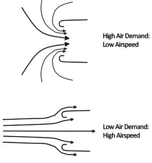
Figure 1. The airflow at the inlet tip changes dramatically as airspeed and the amount of air entering the inlet change.
In the second example, the airspeed is high and the air demand is low. This is a common situation for a cooling-air inlet when the airplane is flying at cruise power with the cowl flaps closed. In this case, the inlet cannot admit all of the air arriving at the inlet face. The excess air spills around the inlet lip. It is moving outward at the lip and must turn around the outside of the lip to remain attached. Changes in angle of attack can produce similarly large variations in the direction of the flow at the inlet lip.
A fixed geometry inlet should be shaped to avoid flow separation both inside and outside over the entire range of conditions it will encounter. The primary way to avoid separation when turning airflow is to turn it gently. For an inlet, this means that the lip should have gently rounded edges. If the inlet lip radius is too small, the lip will stall at some point in the flight envelope. If the stall is internal, poor airflow into the inlet will result. If the stall happens on the outside of the lip, the resulting turbulence will disturb the outer airflow, causing extra drag (See Figure 2).
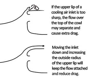
Figure 2. Airflows should turn gently to avoid separation, so proper air inlet shape and placement are essential.
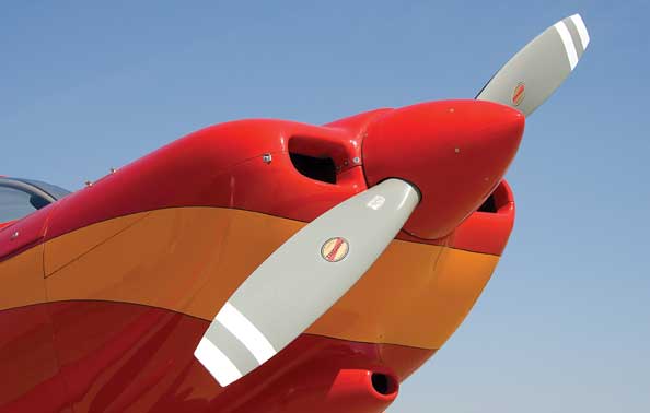
Separation on the outside of the upper lip of the engine cooling-air inlet is a common problem for piston-engine airplanes with flat opposed engines. Because the cooling flow path for these engines is usually downdraft, it is common to place the cooling-air inlets high on the nose of the cowl to make the internal baffling simpler. This placement of the inlets forces the upper lip of the inlet to have a small radius, and to turn through a large angle to match up to the flat top of the cowl. It is also surprising to often see very sharp inlet lips. The problem is particularly common on the engine nacelles of light twins, which tend to be pitched up slightly to increase prop clearance, and operate in the upwash field ahead of the wing.
While such inlets work reasonably well at the low angles of attack typical of cruise, at higher angles of attack the airflow cannot make the turn around the upper lip and the flow separates. This sheds a puddle of stalled, turbulent flow over the top of the cowl, and causes a significant drag increase, a problem that can be eliminated by moving the inlets down and increasing the radius of the outer half of the upper inlet lip. The air will then follow the gentler turn and stay attached.
Another common mistake is to make the corner where the lower lip of the cooling-air inlet meets the cowl too sharp. This can cause the flow going into the inlet to separate and poor cooling will result. A relatively large radius will guide the air smoothly into the cowl.
Inlet Body Shape
The shape of the area behind the inlet can have a large effect on drag. This is particularly true if the inlet is a protruding scoop. The widest point of the inlet body should be somewhat aft of the inlet face itself. This provides a gentle radius to turn air spilled around the inlet aft and get it flowing smoothly over the rest of the airplane. The afterbody aft of the widest point should be shaped like the aft portion of a streamlined body like a wheelpant. The slopes should be gradual, and the scoop should blend smoothly into the skin lines of the airplane.
Inlet Placement
The position of the inlet on the airplane has a dramatic effect on its ability to efficiently take in air. Inlets should be placed in areas of the airplane where the local air pressure is high and the local airflow is nearly normal to the surface. Some examples are the leading edge of the wing, the most forward portion of the nose or cowl and the crease where the base of the windshield meets the nose. A good way to find such local high-pressure zones is to look at the bug splatter patterns on the airplane skin. Areas that accumulate the most bugs are spots where the airflow is coming straight into the skin at nearly right angles. These are likely to be areas of high local air pressure, particularly if the bugs are squished as local dots rather than long smears.
If the inlet is placed in an area where the local flow is moving fast, and is at low pressure, it will perform poorly. Areas of natural low pressure on typical airplanes include the upper surface of the wing, particularly just aft of the leading edge, the sides of the cowling, the top of the cowling and the top of the canopy or cabin. Some designers have a tendency to put scoops or NACA flush inlets on the sides of the cowling to provide engine induction air or to feed oil coolers. In most cases, these inlets perform badly and must be made relatively large, with draggy, protruding scoops, before they provide enough airflow to be useful.

![]()
Barnaby Wainfan is a principal aerodynamics engineer for Northrop Grummans Advanced Design organization. A private pilot with single engine and glider ratings, Barnaby has been involved in the design of unconventional airplanes including canards, joined wings, flying wings and some too strange to fall into any known category.

