Last month, we took a look at some of the problems that can arise when a builder modifies the structure of an airplane in an attempt to make it stronger. We now continue on the same theme with another subject that can have large structural effects—stiffness.
In addition to the strength of a structure, which is its ability to carry load without failing, we must also be conscious of the stiffness of the structure. It’s a common error to confuse stiffness and strength. Strength determines how much load the element can carry before it fails. Stiffness determines how much a structural element will deflect under a given load.
It’s easy to think of a very stiff item as very strong. If you pick something up and apply load to it, and it does not bend or twist very much, it seems strong. Unfortunately, the small deflection under the loads you can exert tells you nothing of the amount of load that will cause the structure to fail.
Modifications that change the stiffness of a structure change the way the loads are distributed into the elements that make up the structure.
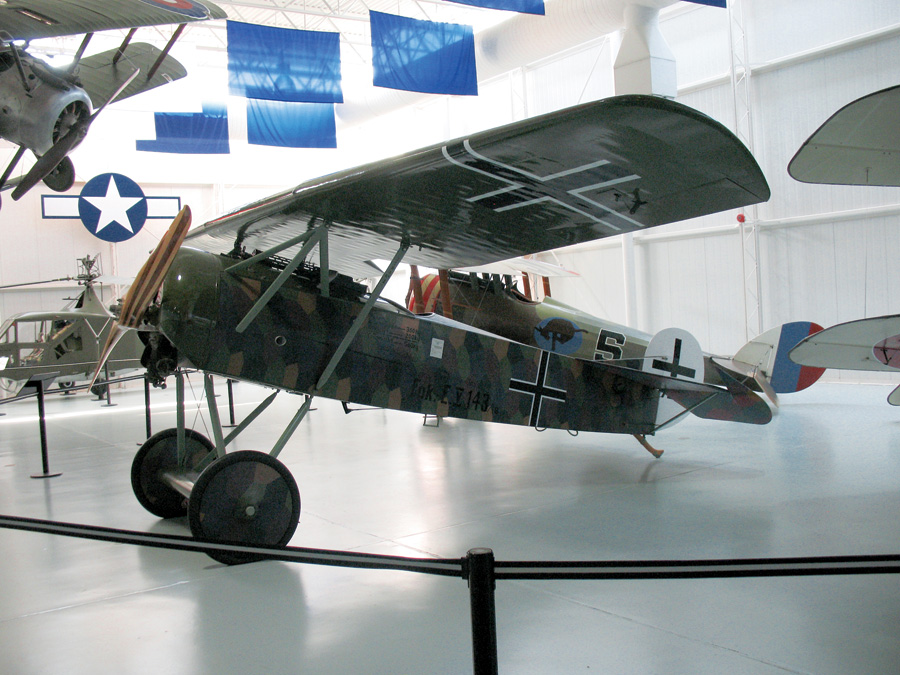
German bureaucrats decided the rear spar of the Fokker D-VIII looked flimsy and ordered it strengthened. This made the rear spar too stiff in relation to the front spar, causing it to fail in pullouts from high-speed dives. After reverting to Fokker’s original design, no further failures occurred. Fokker D-VIII photo by James Emery from Douglasville, United States (Fokker D-8_3975) [CC BY 2.0], via Wikimedia Commons.
Load and Deflection
All structural elements act like springs; they deflect when loaded. The higher the load on the structure, the greater the deflection.
When the stress in the material is below the critical yield stress, the member behaves approximately linearly. The deflection is proportional to the load, and the load absorbed by the member is proportional to its deflection. The stiffer the member, the more load it takes to deflect it a given amount. For an airplane structure, our primary concern is its behavior in this linear range. If the stress exceeds the maximum stress for this linear behavior, the structure will yield and take on a permanent bend if it is made of ductile material like metal, or fail if it is made of more brittle materials like wood or composites.
Load Sharing
Stiff parts of a structure tend to carry most of the load because the less-stiff portions of the structure must deflect much farther before they begin to carry a significant load. An extreme example of this might be the skin on a fabric-covered airplane. When the wing bends, the fabric, which is relatively elastic, will stretch, and carry very little of the bending loads. The spars, which are much stiffer than the fabric, absorb the entire load.
When two structural members are attached together, the deflection of the two members at the point of attachment must always be equal or the two members will move apart. In such a situation, since the two structural elements are constrained to have the same deflection, the load in each member will be determined by its stiffness, and the stiffer member will end up carrying more load.
The following simple example illustrates the effect this can have on the overall strength of a structure:
Suppose we have a weight suspended by a pair of parallel ropes of equal diameter, stiffness, and ultimate strength. Because the two ropes have the same stiffness and are deflected (stretched) the same distance, each rope carries half the load.
If we now replace one of the ropes with a wire, which is the same length as the rope in the unloaded condition and has the same ultimate tensile strength, but ten times the stiffness as the rope, the picture changes. When the load is applied, the wire, because of its greater stiffness, will absorb most of the load without elongating enough to allow the rope to stretch enough to take up its share of the load. In this example, since the wire has ten times the stiffness of the rope, and the deflections of the rope and wire are equal, the wire will end up bearing ten times as much load as the rope. The greater stiffness of the wire creates a situation where the wire is carrying 91% of the load, and the rope is only carrying 9%. The wire is being forced to work much harder than the rope because of the greater stiffness of the wire.
How does this affect the overall strength of the system? The two-rope system will fail both ropes simultaneously, at a total load equal to twice the ultimate tensile strength of a single rope. Because the two ropes have the same stiffness, as well as the same strength, the load will be shared equally between them.
As we have seen, when the rope-plus-wire system is loaded, the wire will be forced to take ten times the load that the rope will take. When the wire reaches its tensile limit and fails, the rope will be carrying a load equal to 1/10 of its ultimate load. The wire will break, and the system will have its first failure at a load just 10% higher than tensile strength of one of the ropes of the original two-rope system. Once the wire has failed, the load will transfer to the rope, which will also fail because the load on the system is above the tensile strength of the single rope. Thus, because of the mismatch in stiffness between the rope and the wire, the rope-wire combination is dramatically weaker than the two-rope system, even though the sum of the tensile strengths of the rope and the wire is the same as that of the original pair of ropes. The difference in stiffness between the rope and wire causes the loads applied to the system to act primarily on the wire, and not be shared between the two load-bearing elements.
While this is an extreme example, situations like this can arise if a builder changes the materials mix in a structure or adds elements intended to reinforce the structure. One such possibility occurs if the builder chooses to mix high-stiffness carbon fiber with less-stiff glass fiber in a spar.
If the original spar has glass spar caps, adding carbon fiber plies to reinforce the spar is much like adding the wire in our example above. The carbon plies are much stiffer than the glass plies and will tend to carry most of the load. They may well fail at a load less than the original maximum load capacity of the wing. If the original glass is still in place, the spar may carry its original deigned load, but will not be stronger than before the carbon was added.
On the opposite case, adding glass layers to a carbon structure does not stiffen it significantly or strengthen it significantly because the carbon is so much stiffer than the glass that the glass will carry very little load. I encountered such a situation during my career when a fabricator arbitrarily added several glass plies to a carbon-fiber wingskin for a prototype UAV because he did not think the as-designed wingskins “felt strong enough.” By the time this was discovered, it was too late to make replacement parts and still meet our schedule, so the vehicle ended up overweight without any benefit whatsoever to its strength from the extraneous glass plies.
Load Transfer
It is important to understand that a structural modification that increases the stiffness of part of a structure may dramatically increase the loads carried by that part and the structure to which it is attached. For example, if one wire of a pair of bracing wires is made thicker, both the wire and the fittings it is attached to will be subjected to higher loads because of the increased stiffness of the heavier wire relative to the other wire in the pair. The thicker wire may be able to carry the higher load, but the fittings, if they are not modified as well, may not.
The same effect will occur if one spar of a multi-spar wing is stiffened.
An illustrative horror story comes from the history of rigid airships. The British R-38 airship suffered some minor in-flight buckling of girders in its mid section during early flight tests. It landed safely, and repairs were made. During the repairs, it was decided to reinforce the bay that had the problems and make it extra-strong. Unfortunately, the increased stiffness of the modified bay greatly increased the loads where that bay joined the next. Shortly after the “strengthening” was completed, the R-38 broke up catastrophically in flight, right at the point where the stiffened structure met the un-stiffened structure of the rest of the ship.
Modifying part of a structure with the intent of strengthening it may accidentally force the modified part to carry higher loads, and these higher loads will not only affect the modified part itself, but the parts it is attached to. If all of the links in the chain cannot withstand the increased loads caused by the stiffness increase, the structure may be weakened overall, rather than strengthened.
Deflection and Distortion
Changing the stiffness of portions of a structure can also change the way the structure deflects when loaded. This can be particularly problematic with wing structures where it is important not only to control bending, but the way the wing twists under load.
If, for example, we were to greatly stiffen the rear spar of a two-spar wing, we would find that the front spar would bend more than the rear spar under load. This differential bending causes the wing to twist. If the rear spar is stiffer in relation to the load it must carry than the front spar, then the wing will twist leading-edge-up toward the tip as it bends. This will increase lift at the tips, shifting the center of load on the wing outboard, and increasing the bending moment on the wing. This process is divergent, and in extreme cases can lead to wing failure. It will certainly decrease the load the wing can carry safely.
Stiffening a rear spar is another example of how a modification intended to increase the strength of a wing can actually weaken it. Late in WW-I Fokker introduced the D-VIII (Yes D-8 not D-7) monoplane fighter. The D-VIII had a series of wing failures caused by this phenomenon. Cantilever wings were a new concept, and the importance of twisting during bending was not well understood at the time. The rear spar of the D-VIII wing was too stiff in relation to the front spar, causing the wing to wash in and fail in pullouts from high-speed dives. Fokker claimed that this was because bureaucrats from the German government had decided the rear spar looked flimsy and ordered him to strengthen it. Fokker complied, and the wings failed in flight. The twisting effect of the reinforcement was eventually discovered by a series of careful static load tests on the wing. Production D-VIIIs reverted to Fokker’s original wing design and no further failures occurred. The D-VIII entered service late in the war, and although only a few saw combat service, it is believed that a Fokker D-VIII scored the final aerial kill of the war.

![]()
Barnaby Wainfan is a principal aerodynamics engineer for Northrop Grumman’s Advanced Design organization. A private pilot with single engine and glider ratings, Barnaby has been involved in the design of unconventional airplanes including canards, joined wings, flying wings and some too strange to fall into any known category.


