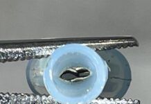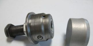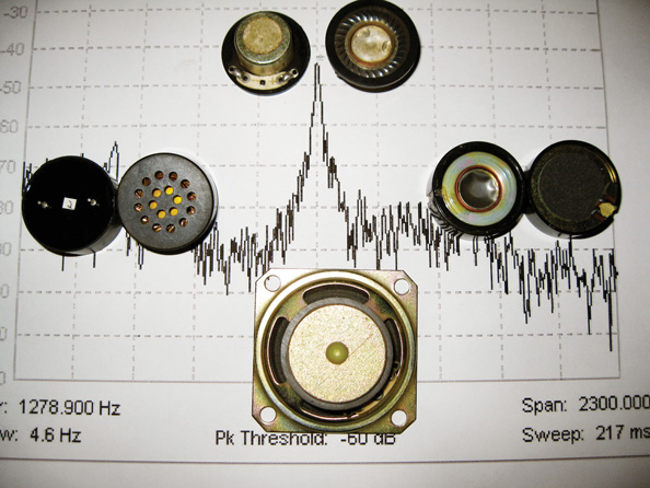
Clockwise starting far left: small semi-enclosed speaker
With all due respect to Bill Haley and the Comets (and Elvis), who recorded this rock classic in the mid-1950s, our version of this vibratory model will concern itself with a propulsion system that is converting petrochemicals into noise, vibration and thrust simultaneously.
Say what? In the vernacular, the engine/propeller combination is burning, shaking and rolling. The burning is fine (it makes us power) and the rolling is fine (it pulls us through the air), but the shaking is bad (it wears out and cracks other parts). The thrust (pardon the pun) of this series of articles is to try to figure out how to measure and correct the vibration in our firewall-forward propulsion systems.
Honestly, Ive been thinking about an inexpensive vibration measurement system since my days as an applications engineer at Spectral Dynamics (www.spectraldynamics.com) vibration measurement company. In those days we had thousand dollar sensors, tens of thousand dollar instruments and hundred dollar an hour consulting engineers. If you have access to all of this vibration analysis equipment, read no further. If you want to do it on the cheap, read on.
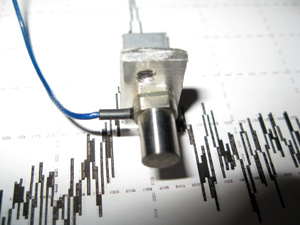
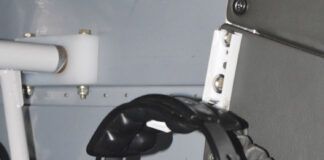
A professional accelerometer mounted on an aluminum L-bracket of the $250 to $500 variety (on loan from Bentley Nevada). The background is a vibration plot in the frequency domain.
Vibration Analysis
There are two components of vibration. One is an imbalance in the engine internals (pistons or rods that werent mass balanced during engine assembly or differences in combustion pressures), and the other is an imbalance due to more metal on one blade of the propeller than the other. Both are bad, but the prop imbalance is more easily corrected.
How do we tell whether the shaking is due to engine or propeller? Quite simple: two tests. One is that engine shaking is almost always horizontal (side to side) in an opposed engine, while propeller shaking is at any angle. If the vibration sensor picks up a vertical component, it is most likely propeller, while the horizontal component can be either propeller or engine. A simple subtraction for the second test to remove the propeller horizontal component from the engine component should allow detection of both vibration components separately.
Now let’s talk about how we are going to detect the vibration. A little minutes:seconds math tells us that if the propeller is rotating at 2400 rpm or so, then the propeller is rotating 40 times a second (2400/60). That means that the vibration is going to have a 40 Hz (40 cycles per second) component. We ought to be able to sense that vibration with a relatively simple sensor that responds to 40 Hz.
What does 40 Hz sound like? Well, we are pretty sure that the stuff coming out of the wall socket is 60 Hz, and most of us have heard an electronic component that isn’t filtered very well humming along at that rate, so it is just a low-pitched hum. What we need is something that will respond to that hum and turn it into an electrical signal. Once we get that electrical signal, the rest is a relatively simple circuit design.
So what kind of inexpensive device will put out an electrical signal when it is shaken? In my mind there are three classes of devices that will fill this bill; it remains for the experimentation to see which one will work best.
Three Options
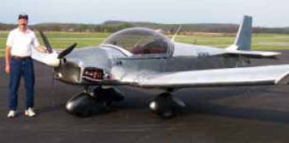
Research [experimentation] is what I am doing when I don’t know what I am doing (Wernher von Braun). I honestly haven’t ever done this sort of experimentation before, and the RST flying test bed (the Cessna 182 A model) is still in pieces, so this series of articles may string itself out over the next year or so. I wont have the opportunity to get the airplane up and running for at least another month or two, and then we are into the dead of winter with all of the stuff that entails (like frozen fingers and mushing through snow), so it may take awhile to get good data. Be that as it may, here are the three paths Im going down.
One, a plain old speaker will produce hum if you provide it a driving signal. However, speakers are reciprocal devices that will produce a signal if you vibrate the speaker cone. One problem with this approach is that a regular speaker has openings front and back. Whats the problem? There is a very loud sound source located close to the engine (some might call it a bark) that will vibrate that speaker cone from the back side: the sound of the exhaust stacks. That loud sound may drown out any tiny vibration signal that we are picking up. We may be able to filter out the exhaust frequency (double the prop frequency for a four cylinder and triple the prop frequency for a six cylinder), but I really don’t want to have any nonlinearity in the mechanical speaker cone to mess up my results.
One solution for this problem is to use a speaker with a sealed back and mount the speaker face down onto the engine mounting bracket. That way it will be simply the vibration of the mechanical mount attached to the engine that will give us the electrical signal proportional to vibration rather than the sound of the exhaust stack. Of course, I am going to give the output of the sensor (whichever way I proceed) some type of filtering to keep noise out of the system, but I would prefer to put as little stress on the filtering as possible.
The second path I am considering is the use of a microphone element as the sensor…to be exact, an electret microphone element. Why? Because dynamic elements have the same problems as speakers: They are nothing but a speaker optimized for voice. The electret element is sealed at the back, so practically no outside noise can get into the element if we put the element face down onto the mounting bracket.
The third way I am going to experiment with is the use of piezo (pee AYE zoh) elements, and these take two forms. One is our old (and very obsolete) friend the phonograph cartridge. The nice part about using a phono cartridge is that it has nearly zero response to loud audio (exhaust) sounds. The bad part is that they are hard to come by, so if this is the route that works best, Ill have to find you a source for them.
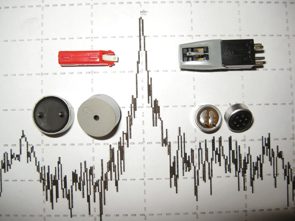
Piezo elements, clockwise starting far left: piezo speaker, monophonic phono cartridge, stereo phono cartridge, electret microphone element.
The second part of the third way may combine the best features of all three methods. That is, a small piezo speaker element that is completely closed, doesn’t require a power supply (the electret element does) and can be easily mounted to the engine mounting bracket using an adhesive of some sort. (Im going to try double-stick tape on all of my first-shot tests.) They are cheap (less than a dollar in onesies) and readily available.
As you can probably tell, Im pretty shot up about this series of experiments and articles. It has been a long time since Ive done an experiment when I didn’t have a pretty good idea of what to expect as the result. Stay tuned and we’ll learn together.


