A couple of weeks ago, one of the folks on the newsgroup forum I monitor (www.pilotsofamerica.com) wailed and whined that the iPad that (s)he wanted to run from the 12-volt aircraft system required adapters that cost over $300 to buy. A couple of others said that was peanuts-28 volt system adapters were double that-when you could find them.
Good heavens. Nickels and dimes’ worth of silicon and a little soldering is worth that kind of money? Let’s talk seriously about using voltage regulators and other power circuits to do your jobs for you. This is not going to be a one-circuit-fits-all, but a conglomeration of different ways of solving individual problems.
One problem that raises its head quite a bit is how to provide battery backup to a circuit so that if the primary power is disconnected the backup battery automatically powers the circuit for as long as the battery lasts. Here is an easy way to provide as many power sources to a circuit as you wish with the highest-voltage circuit being the primary power supply. This is how it works (see Figure 1):
Let’s say that the aircraft battery is connected. At 12 volts it is the highest voltage of all four sources, so D1 is forward biased and current flows from the aircraft battery through D1 to power the circuit. Simultaneously, D2, D3, and D4 have more voltage from the 12-volt aircraft battery on their cathode (vertical stripe) end than their anode (black triangle end) and are back biased and shut off. If the aircraft battery fails, then the 9-volt transistor radio battery takes over; if the transistor radio battery runs out of juice, the solar cell battery takes over; if it is a cloudy day, you had best hope that you fed the hamster that morning. Note that all the power sources have a common connection from their negative lead to the circuit’s ground lead.
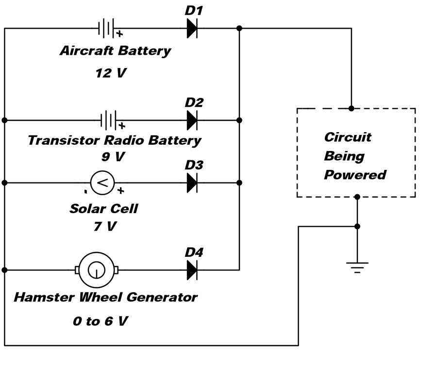
Figure 1: The aircraft battery plus three backups. If the aircraft battery fails, the transistor radio battery powers the load; if the transistor radio battery fails, the solar cell powers the load; if the solar cell fails, the hamster starts running.
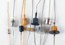
The diodes themselves can be sized to fit the application. The venerable old 1N4148 or 1N914 (2 each) can be used up to 300 milliamperes, but at 100 mA the forward voltage loss across the diode is nearly 1 volt. Thus, a 12-volt supply will only be 11 volts at a circuit that draws 100 mA. For higher currents the 1N400x (where x can be 1 to 7) (3 each) can be used up to 1 ampere. At 1 ampere the voltage loss across the diode is about one volt also. If this amount of voltage loss is too much for your circuit, you can use a Schottky diode such as the 1N5817 for 0.3 volts of drop at an amp, and at a dime apiece.
Now let’s solve the original $300 power supply problem. The problem comes down to powering an iPad (or other electronic device) that needs a lower voltage than the aircraft system uses. In the case of the iPad, it means that we need to supply 5 volts (regulated) from the aircraft source. That particular conversion is pretty easy as 5 volts is a very standard voltage for digital electronics. Before we begin, though, a word of explanation. The device I am going to use first (and change in the May issue because I forgot something) is a 5-volt 1-ampere voltage regulator. Lots of confusion with this rating. Yes, it regulates battery voltage down to 5 volts, but it does not force 1 amp of current into your circuit. The better way of giving this specification is that it is a 5 volt and up to one ampere of current. If your device only requires 500 milliamperes (0.5 amps), then the regulator only puts out 500 mils.
Let’s take a look at the circuit (Figure 2). The heart of it is U1, a plain old 7805 regulator (29 in single quantities at www.jameco.com). C1 is a common 100-nanofarad (0.1 microfarad) disk ceramic capacitor (also 29 at jameco.com). C2 is a common 10-microfarad electrolytic capacitor (9 each, but you’ve gotta buy 10 of them at a time from jameco.com). D1 is a common 1-amp rectifier diode such as a 1N400x, where x is any number you choose from 1 to 7 (5 each, but once again, you’ve gotta buy 10 of them at jameco.com). What do each of these parts do? The regulator takes the aircraft battery voltage down to 5 volts 4% (4.8 to 5.2 volts). C1 keeps the noise and oscillations out of the front end of U1. It can be any voltage you like so long as it is more than battery volts. However, for best performance it should be very near (within an inch or so) of the input pin of U1. C2 keeps any noise generated in U1 from getting to the output. A 16-volt capacitor would work well here, but any working voltage from 10 to 20 will be just fine. Note that C2 is polarized and must be installed with the + lead to the positive output 5-volt line. D1 is there to prevent what is called fortuitous reverse voltage, or a voltage that somehow gets onto the 5-volt output with the input leads shorted together. Don’t laugh. It happens. Murphy is alive and well.

Figure 2: A very simple aircraft battery (12/24 volt) to 5-volt converter. Most of the consumer stuff (cell phones, tablets, pads) runs from 5 volts.
Oh, did I say that the aircraft battery had to be 12/14 volts? Nope. This handy little device can work up to 35 volts at the input, so a 24/28 volt system will work just fine with this one caveat:
This sucker is going to get hot! How hot? Well, if we run it full-to-the-wall at 1 amp output, it will dissipate 9 watts with a 14-volt battery and 23 watts with a 28-volt source. That is going to be spit-sizzle hot for either one. The good news is that the IC is thermally protected and will shut down (no current output) when the temperature gets to internal limits. The bad news is that the IC will shut down at the most inopportune moment (Murphy’s Law of Thermal Gotcha). Our problem is to keep it from getting that hot.
So far we have about 73 in parts, and if we are going to beat that $300 price tag, we’ve got $299.27 to play with. That’s going to buy an awfully big heat sink. However, at this point we leave the realm of electronic tomfoolery and enter into your personal requirements. Just say this: The metal tab of U1 is also connected to the ground (“common”) lead and the metal tab is the thing that needs to stay below the boiling point of water (which, by the way, is where we get the “spit-sizzle” test-if you wet your finger with spit and touch the case, and if it sizzles, then the spit is boiling and the IC is running too hot). If you mount this circuit inside of a metal case and bolt the IC metal tab to the case, you will probably have enough surface area on the case to keep the IC cool enough. If, on the other hand, the case gets spit-sizzle hot-poof. As to the metal case, c’mon, you are building airplanes. You can’t build a small aluminum box?
“But Jim,” you say, “my little electronic goodie needs 9 volts, not 5.” Not to worry. Three modifications to our fixed 5-volt supply and you can have anything you want from 5 volts to (battery volts minus two). That is, with a 12-volt supply, you can have 5 to 10 volts adjustable, with a 24-volt system 5 to 22 volts, and so on. No big deal-take a look at Figure 3.
The addition of R1 allows you to set the voltage between the limits in the last paragraph anywhere you choose. D2 is there to keep the same fortuitous foolishness we discussed above from destroying U1.

If primary power is disconnected, it is possible to automatically power a circuit using an alternate power supply for as long as the alternate source lasts.
The third modification is not quite so simple. Since the tab is connected to common as described above, and if we want to get heat out of the tab to keep U1 within limits, somehow we are going to have to thermally connect that tab to the metal heat sink, but electrically isolate it from the sink. Not a real problem; you simply need a “heat sink mounting kit” (8 each, but you’ve got to buy them in 50-packs for $4, at jameco.com), which is nothing more than a hyper-thin mica washer, a #4 shoulder washer, and a 4-40 nut and bolt. It helps to use thermal compound on both sides of the mica washer with a couple of side notes:
The thermal oxide stuff you buy at electronics parts stores is relatively expensive ($5 for a small tube), but you can get the same stuff from the drug store as zinc oxide, the white cream you put on your nose to keep from sunburn.
The stuff is real tough to keep off of your skin and your clothes. Being a very good insulator, it is also very impervious to soap and water, so cleaning it when (not if) you get it on yourself is difficult.
I’ll keep this thread going in a couple of months with the higher current that the iPad requires and perhaps a venture into switching supplies. Next month (April) I’m going to announce a new way of building the venerable cotanger antenna, a real workhorse for almost any antenna application. Until then, stay tuned…

![]()
Jim Weir is the chief avioniker at RST Engineering. He answers avionics questions in the Maintenance Bay forum at www.pilotsofamerica.com. His wife, Cyndi Weir, was his high school sweetheart 50 years ago and now she keeps Jim from making stupid blunders in spelling and grammar. Check out www.rst-engr.com/kitplanes for previous articles and supplements.


