When last we left this project, we noted that the little speaker-turned-microphone would do a pretty good job of turning the cell-phone ringtone into audio we could use to drive some digital circuitry and, through a relay, power up any number of devices.
I thought the digital circuitry would be the easy part. What a surprise to find that it fought me tooth and nail for the better part of a solid week. If you see my editor at Oshkosh this year, you might want to buy her a beer for giving me the extra time to make this thing work.
I’ll give you a relatively thorough explanation of why I did what I did with this project, and then next month I’ll explain what goes into it, stage by stage. By the way, don’t even think about starting construction on this device without a decent oscilloscope at your command. If you attempt to troubleshoot this circuit with a multimeter or by osmosis, it just won’t work.
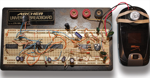
This is the entire circuit, complete with output relay (just below the word ARCHER on the construction board). The LM354 op-amp is the integrated circuit on the far right, then in order (right to left) are the 4017, 4071, 4013 and the 4020. Think haywire if you will, but almost all first-cut prototypes look something like this.
Inputs Here, Outputs There
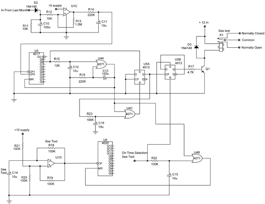
Let’s take that 10-volt peak-to-peak audio signal and turn it into a digital pulse for processing. U1C is called a “comparator.” It compares the voltage of the (-) inverting input with the (+) non-inverting input. If the voltage on the (-) inverting input is greater than the voltage on the (+) non-inverting input, the output (pointy end of the symbol) is ground (zero volts), or in the digital world, what we call a “logic low.” Conversely, if the voltage at the (+) input is greater than the voltage at the (-) inverting input, the output is nearly supply voltage, or a logical high.
D2 takes the pulses from last month’s amplifiers and charges C10 to the positive peaks of those voltages. Since last month’s amplifier sits at a quiescent (no signal) voltage of half the supply, the (+) input of U1C is about half the supply, less a 0.6-voltage drop across D2. This puts the (+) input lower than the (-) input, and the output is logical low.
Along comes a “ring” signal from the hangar cell phone, and now all of a sudden the voltage across C10 rises to nearly supply volts. The output snaps from logical low to logical high, and R13 assures that this voltage does not swing back during the ring cycle. Then the ring subsides, and the output returns to a logical low. The next ring takes it back to logical high, and the process repeats itself for each ring of the phone.
R14 and C11 take these low-high pulses and remove any “trash” (spikes, noise, etc.) from them, outputting a clean one pulse per ring to the digital circuits.
U3 is a simple divide-by decade counter. At the output of Q0 (20 = 1), you have a logical high for a single pulse on the CPO input. Then a logical high for two pulses from the ring counter at Q1, and so on until you get to Q8, where you get a logical high for a phone ring of eight pulses.
U4A is what is called a pulse stretcher. When I get eight ringtone pulses from my phone, I want everything that happens in the outside world to be shut off. U4A is an “OR” gate, which says I don’t care if there is a logical high on input 1 OR input 2, I’ll give you a logical high output (the pointy end again) if either of these two is high. So along comes ring eight and sets one input high through R15 and C12 (noise filters again). Pow goes the output high and holds the other input high through C13, no matter how many rings come through the phone. It resets U3 to a zero count and sets one input of U4A to reset U5A to zero after a short time, determined by R15 and C12.
The schematic.
On the Eighth Ring
Meanwhile, that eighth pulse from U3 sets (S) U5A Q output high. Since U3 has been reset (MR) through U4A and is held reset for about 20 seconds by C13 and R16, U5A has been reset (R) so that the Q output of U5A has gone low. But for the brief time that the Q output of U5A went high, it clocked a pulse (CP) into U5B and set the Q output of U5B high. This high output, applied to the base of Q1 through R17, turns Q1 on and pulls relay K1 contacts “Common” and “Normally Open” together, completing the circuit.
In another part of the circuit, U1D is a one-pulse-per-second, free-running oscillator. The output of U1D is applied to the clock pulse (CP) input of U8, which is a true binary counter where the Q outputs 1 through 13 go high when a certain number of pulses arrive at the clock-pulse input. How do we calculate how may pulses it takes to turn on a particular input? Let’s arbitrarily take a Q output, say, Q11. Q11 will provide an output when 211 pulses are counted from the CP input. How long is that? If the clock gives one pulse a second, 211 is 2048, so it will turn on in 2048 seconds, or about 34 minutes. What is the maximum time allowed? It’s 213 seconds, or about 136 minutes (about 2.25 hours).
When U4A output went high on the eighth ring, it turned on U4B, which reset (MR) U8 to zero. When C13 and R16 discharged to turn U4A off, that in turn turned off U4B and allowed U6 to start counting up. When it reached the number of seconds the user selected by connecting the free end of R22 to one of the U6 Q outputs 0 to 13, it set U4B high again and reset U5B Q output low, turning off Q1 and allowing the relay to de-energize, and connecting Common to Normally Closed.
One feature, not quite obvious from the selection of the Q-bar (not-Q, or the opposite of Q), is that U5B is a true flip-flop. That is, one pulse on the CP input sets Q high, and the next pulse sets it low. If the cell phone gets another eight pulses during the timer “on” mode, it will set the Q output low and turn off Q1 and the relay K1. Thus, the operator may interrupt the timer and turn the timer on and off at will.
Say you want a longer or shorter time span. No problem: By varying the values of R18 and C14, you can vary the clock speed of U1D to nearly anything you want. How do you calculate the time of a single clock pulse from U1D? Simply multiply the values of R18 and C14 together. Using the values given in the schematic, multiplying 100,000 (100K ohms or 100 x 103) x 0.000010 (10 microfarads or 10 x 10-6) gives the answer 1 (1 second). If you raise the value of R16 to 1M (one megohm) and leave C14 as 10 microfarads, you have increased the clock-pulse time to one pulse every 10 seconds, and now the maximum time of the circuit is 213 x 10, or almost 23 hours (a little shy of a day). If you increase R16 to 1M and also increase C14 to 100 microfarads, you now have a timer with a maximum on time of 9.5 days.
Next month we’ll look at each step of building this little goodie. I’d advise doing it the professional way…stopping after each step to see if what you did matches what you thought you should see along the way. Or you could do it like my students do at the beginning of each semester—put it all together, complete with mistakes, and then spend the rest of the semester pulling it apart, trying to find the errors and correcting them one by one. It’s a lot faster my way, but it’s certainly your choice.


