 After seeing Ted Miller’s article, “How to Rewire a Nippondenso Alternator for External Regulation,” in the March 2019 issue of KITPLANES®, I decided there had to be a simpler way to modify an ND alternator. This alternate method requires no major surgery. There’s one minor modification, enlarging a brush-holder mounting hole, but this does not prevent the alternator from being returned to its standard configuration.
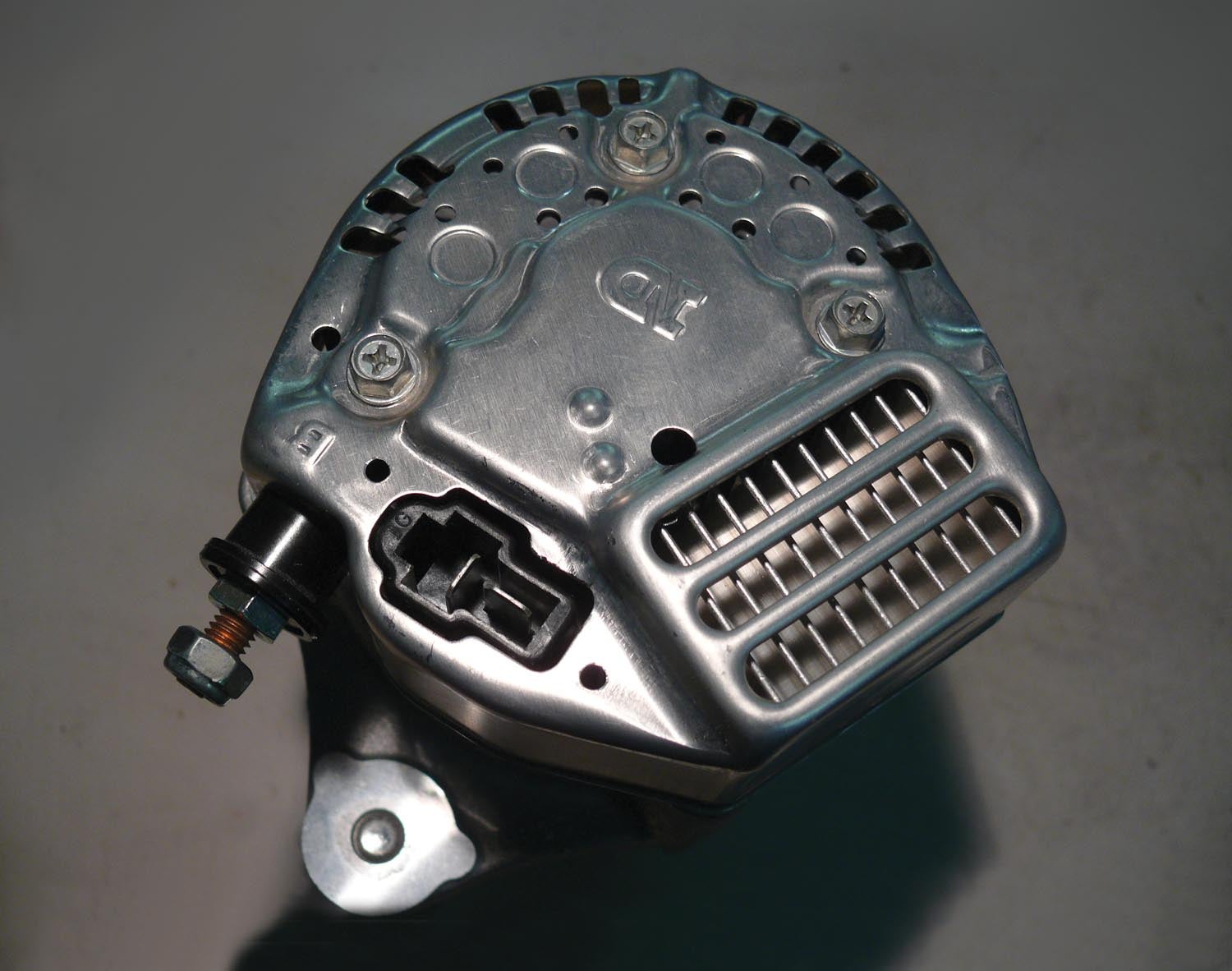
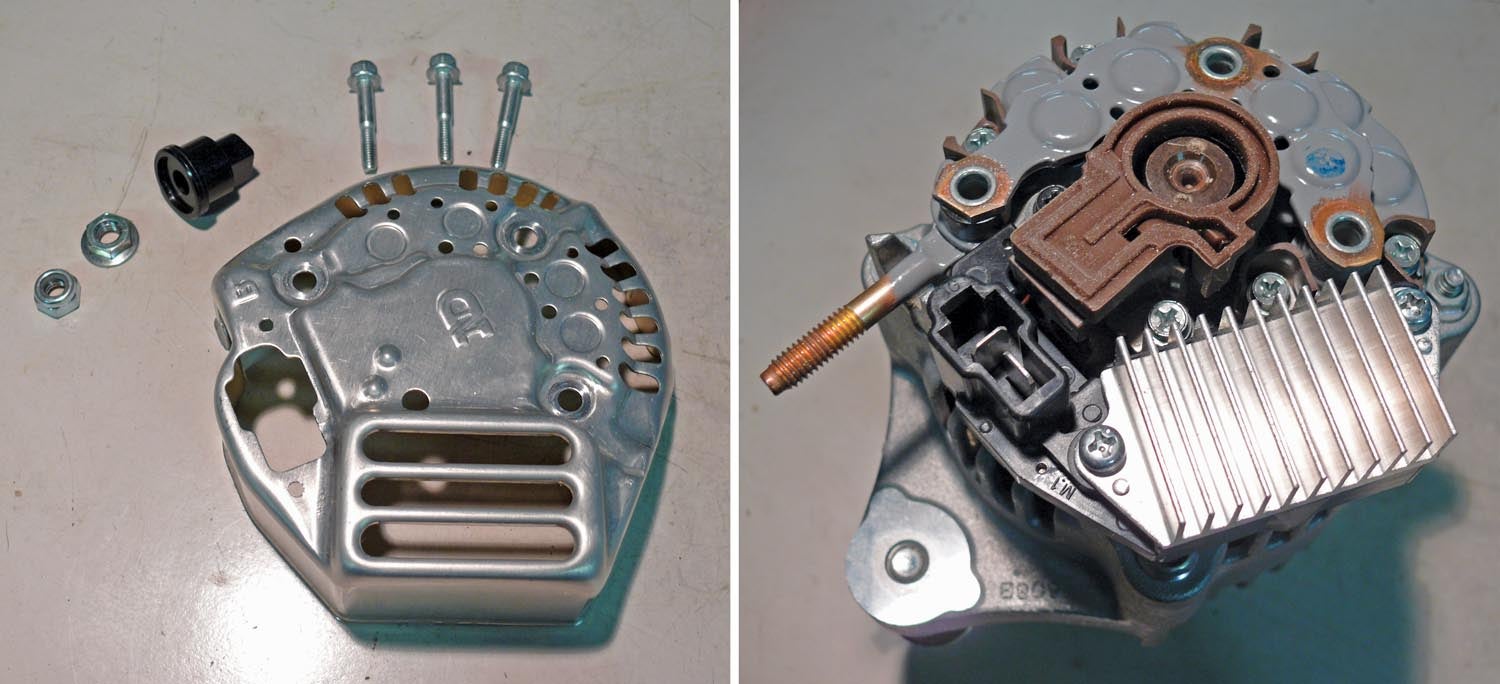
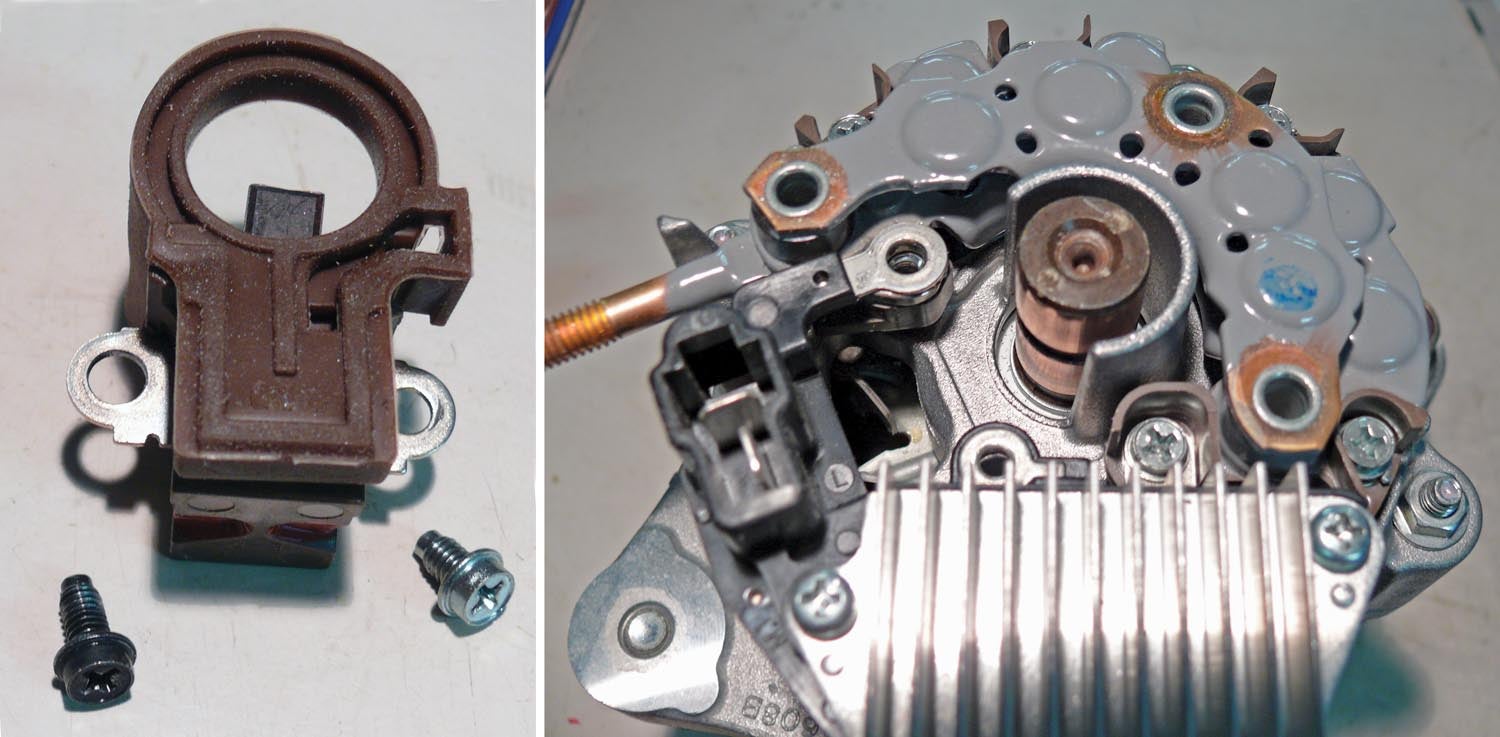
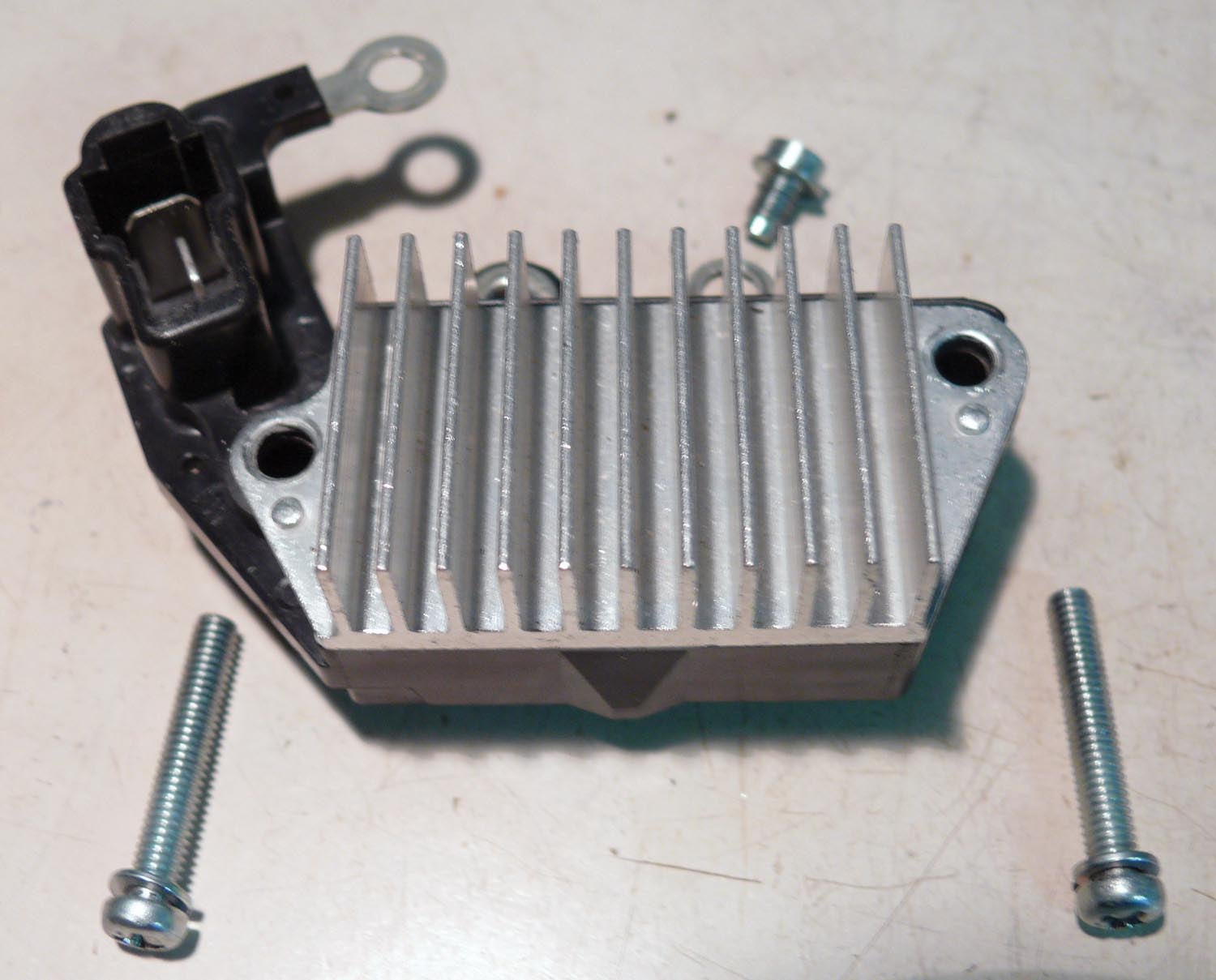
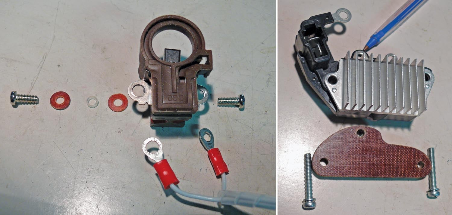
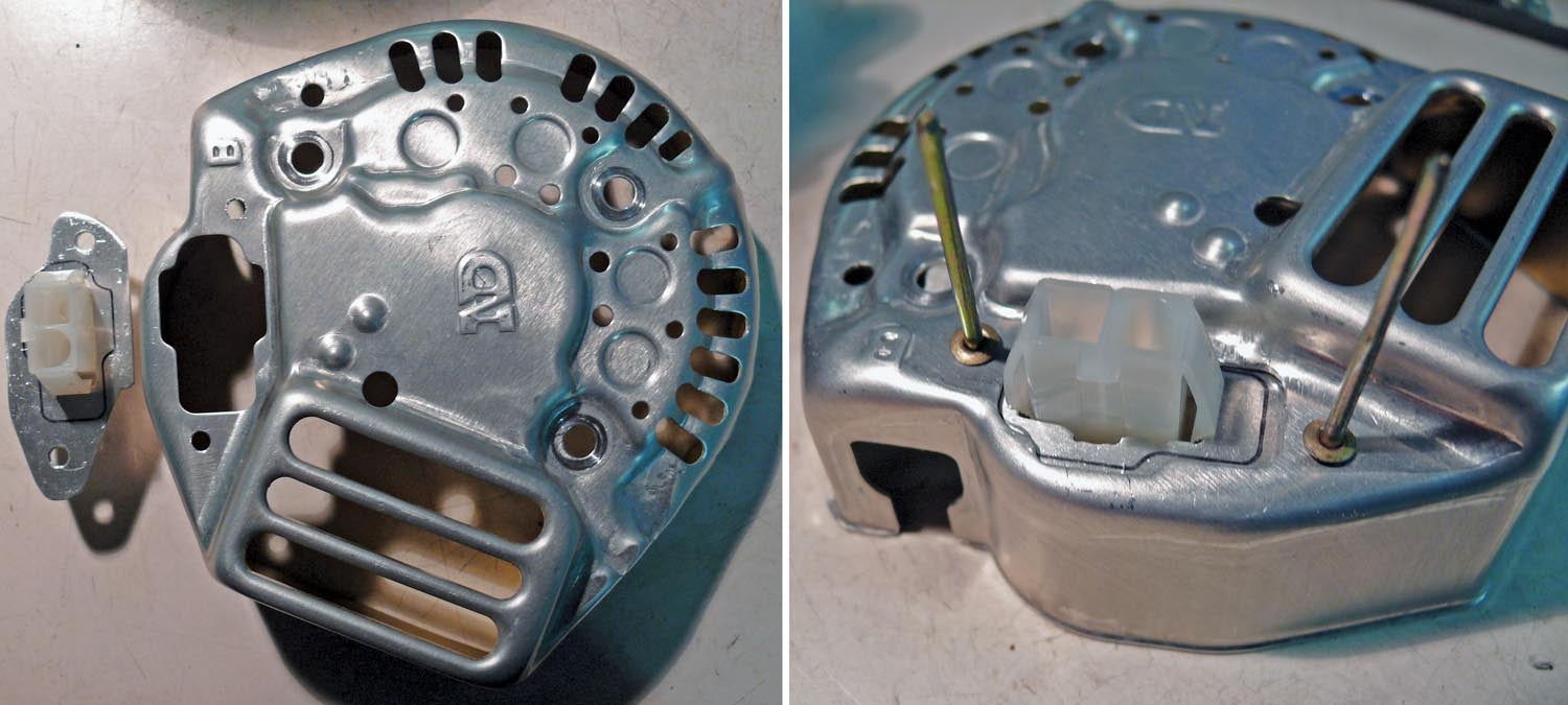
Starting with the standard alternator, remove the terminal shroud and end cover to expose the brush holder and regulator. Next, remove two screws to release the brush holder, then remove three screws to release the regulator. The two long screws will be reused, but the third screw is not used again.
The only (tiny) modification to the alternator is to ream out the left-hand mounting hole of the brush holder to 5 mm. As mentioned earlier, this will not prevent the alternator from being restored to standard. This minor mod is necessary as the wire to this terminal on the brush holder must not contact the frame or output terminal of the alternator, or the magic smoke will escape!
The new components are two M4x10-mm screws; two fiber washers with 4-mm holes; one small piece of nylon tube (or equivalent), OD 5 mm, ID 4 mm, and a length of 1.5 mm; and two 18-gauge terminated wires.
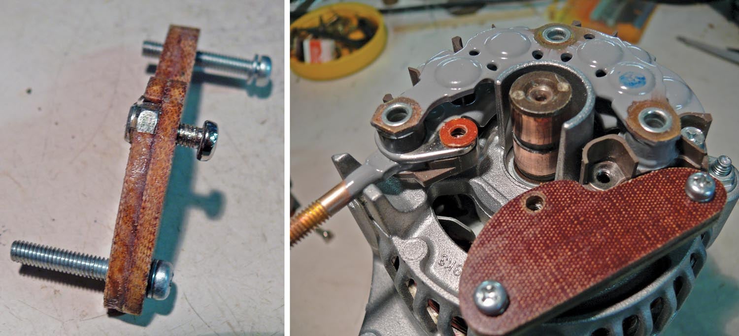
A mounting block (phenolic, canvas Bakelite, etc.) replaces the regulator with three holes: two for the original mounting screws and one with a captive nut to become the right-hand mounting point for the brush holder. This block is 1/4-inch thick and precisely replaces the regulator after being cut to shape. I used two 1/8-inch thick pieces epoxied together and holding the nut. Alternatively, use a ¼-inch block, drill a 3.3-mm hole, and tap for M4. Mount this on the alternator, and put one fiber washer where the left-hand brush holder terminal was attached.
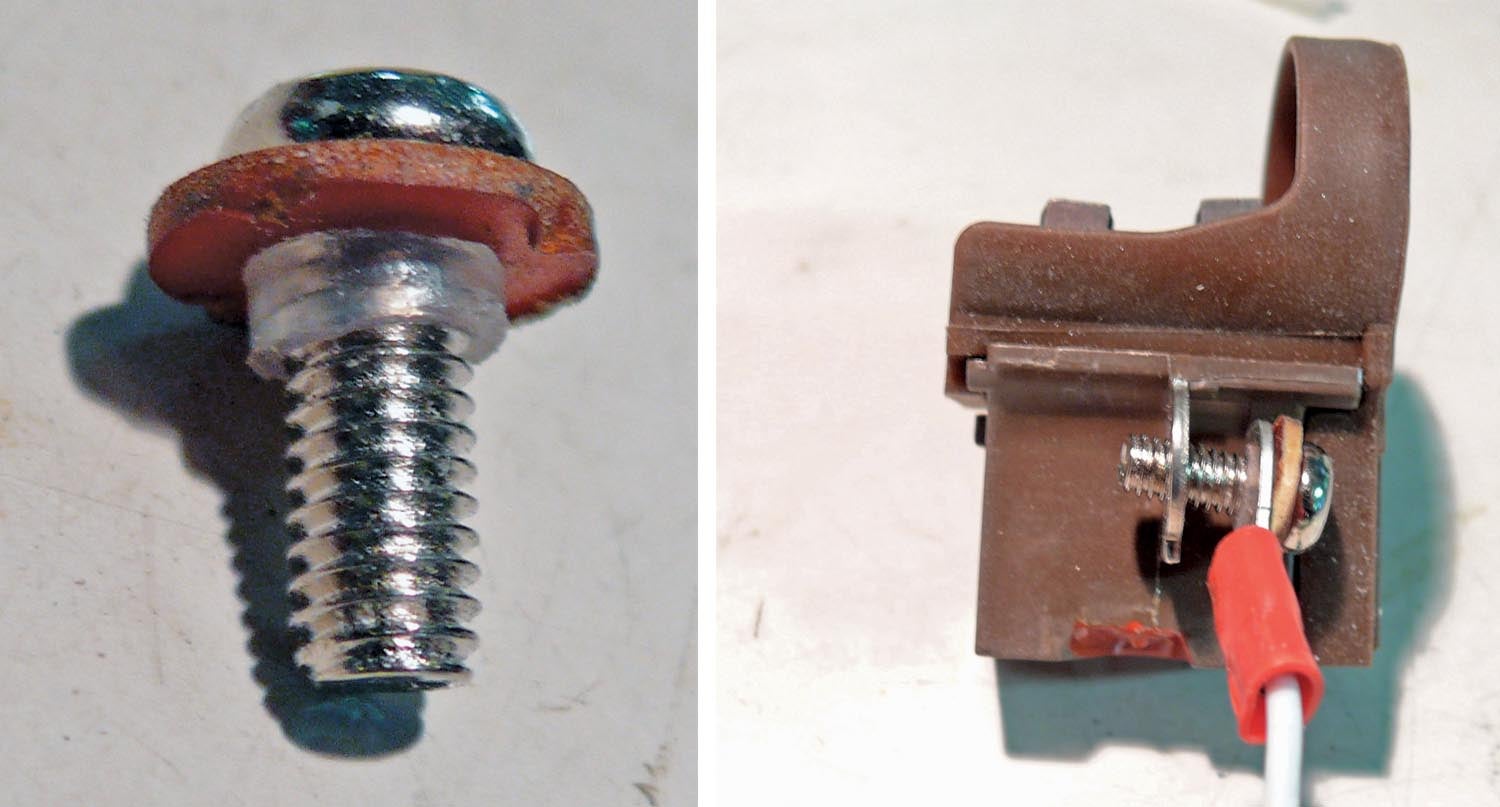
Assemble one fiber washer and the nylon tube on an M4x10-mm screw, then add a new wire terminal with a 5-mm hole, and fit the screw into the now 5-mm hole in the brush holder. Mount the brush holder on the alternator with the right-hand new wire under the brush-holder lug. This keeps the brush holder precisely level and only a tiny fraction higher than the original position.
Conduct a test to ensure that neither wire is in contact with the alternator frame or the output terminal. These two wires go to the external regulator; one will get grounded or connected to 12 volts depending on regulator type, but do this at the regulator. I used a B&C LR3C-14 regulator, and thus one wire is connected to ground at the regulator.
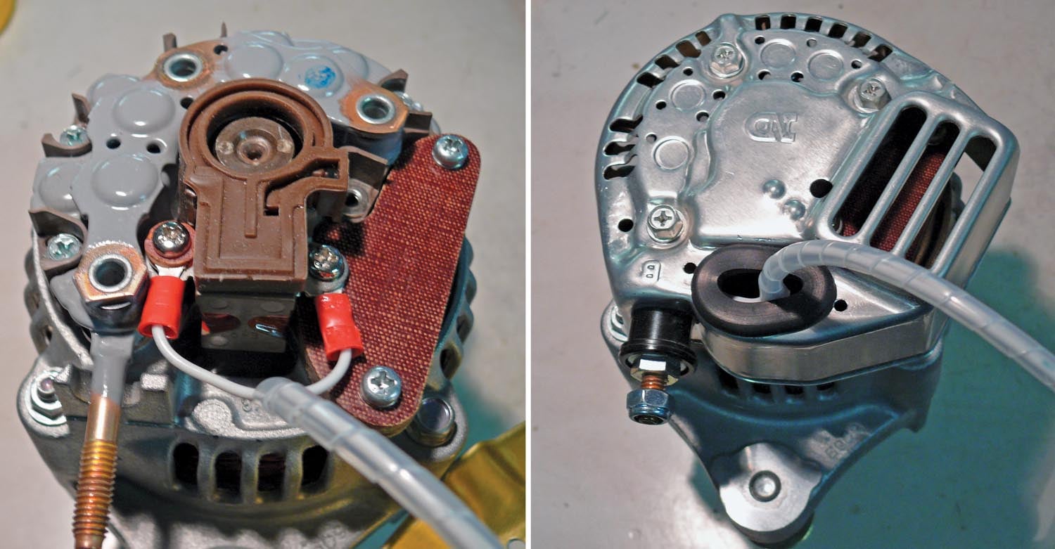
Fit a rubber grommet to the opening on the alternator rear cover, thread the wires through, and refit the screws and terminal shroud that were previously removed. Be sure to protect and terminate the two wires as necessary. An alternative to having wires coming out of the cover is to mount a Molex-style terminal in the cover, and attach it with two pop-rivets.
Done! And remember that the alternator can be returned to the standard configuration at any time.


Graeme- Wonderful article!! Would it be possible to get the exact Model and part # of the alternator that you used?
Thanks
Jim, it looks very much like the one called out in the article referred to in the first sentence of this article. “Lister #14684 originally for an ‘85-‘89 Suzuki Swift.”
The only ID on the alternator is the logo on the back cover. This alternator is on my Viking 110 HP engine which is based on a Honda Jazz. I don’t know if this alternator is from that engine; ask Viking.
Graeme.
I have done this conversion but the B and C external regulator schematic only shows that it needs the field wire (positive wire of the slip rings). The ground (negative wire from the slip rings) looks to be grounded to the case of the alternator. Does this matter any?
No matter; I brought out 2 wires so as to ground the second wire at the regulator.
Which wire is ground and which is field in your photos??
The two wires are the two field brushes and are both brought out so that one goes to the regulator and the other is earthed at the regulator. It doesn’t matter which wire is which.
Graeme
Could you explain why the left terminal on the brush holder is insulated from the positive pole of the alternator? Is that to allow some isolation for safety? What might happen if it is left in contact and a ring terminal/wire connection to the + of the regulator? The rest of your solution is really great but the tube/washer in my opinion seems possibly prone to failure. Thanks for this.
Hi Graeme,
I have an automotive ISKRA IA O 0507 alternator for my RV8 Lycoming O360.
This alternator is internally regulated, and has D+ connexion, no Field .
I have vertical power, and field is requested to manage alternator .
Do you thing there is way to modify alternator to get field connexion?
Great thanks
Best regards
Dominique
Comments are closed.