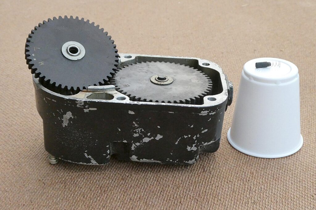
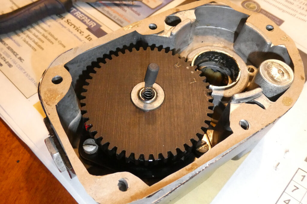
![Making rare use of my drafting tools for the internal timing. [All Images Credited to Andrew Robinson]](https://www.kitplanes.com/wp-content/uploads/2026/05/P1010535-1024x682.jpg)
Internal Timing
Setting the internal timing is supposed to make use of a special plate with degree markings and a pointer that clips to the end of the breaker cam. Not having said tool, I improvised. My college drafting protractor (required for one of the last analog drafting classes before they all went digital, thank you) was used to make 10, 15, and 25 degree marks on the casing, and a short straight-edge nestled in the screw slot worked as a pointer. With the red mark on the timing gear showing in the case opening, you are to then turn the armature backwards a few degrees until the magnets “pull-in” and hold the armature in a “neutral position”, as the manual describes it. With everything assembled, feeling this neutral position wasn’t quite as easy as with everything dry, but it’s there, and you’ll still be able to see the red gear tooth in the window, albeit off to the side by about one tooth. The pointer tool is then pointed at zero degrees; in my case, I marked a de-facto zero line.
At this point, so to speak, the overhauler is instructed to turn the mag in its normal direction until the pointer is at the ten degree mark and the points are adjusted to just begin opening. Not having the pointer tool, I used my straight-edge to note the nominal zero mark and my handy protractor to show me where +10 degrees was. Nor did I have the timing light tool to determine that the points were just beginning to open, but I did have an old-timers trick from one of the forums: adjust the points just enough that they “turn loose” of a piece of cellophane from a cigarette pack. Having left my ciggies in 1980-never-done-that, I looked around and found a restaurant toothpick still in its cellophane wrapper. Score! The mag is then turned further in its normal direction until the points are at max opening and set to a gap of 0.018 +/- .006 inches. So the purpose of the original cellophane gap setting before that? Beats me, other than determining where the points are just beginning to open. A timing “buzz box” was later employed to set the overall timing once mounted on the engine.
Does it work?
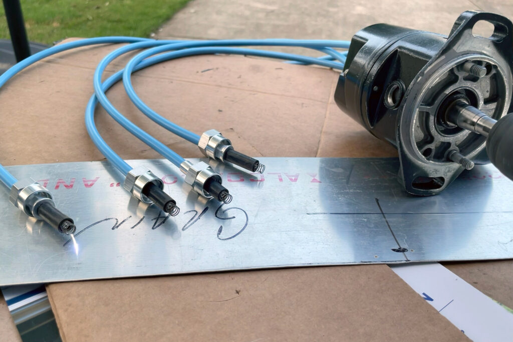
I had followed the instructions to the letter (more or less), but I wasn’t sure if it was going to work or not, so I headed out to the garage, installed the ignition harness plate, and hooked up the spark plug wires. With the mag sitting on a sheet of aluminum and the plug leads laying on the same sheet, I gently chucked a cordless drill onto the end of the armature and spun it. Lo and behold, there were sparks! Nice, big, healthy sparks emanating from a “bitsa” magneto. Sweet! Cue the mad scientist proclaiming “It is alive!” or Snoopy doing his happy dance. Your choice of visuals. Testing in a similar manner is advised so that the spark energy has somewhere to go, and not back into the mag or into you.
Ahead on impulse power
Just like the starship Enterprise, our engines briefly run on impulse power.
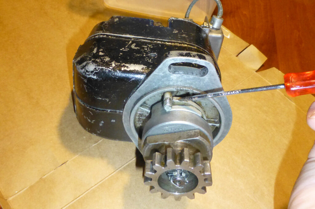
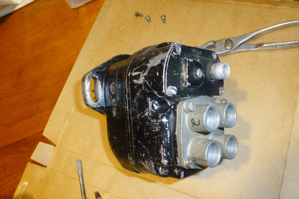
The impulse coupling comes into play to provide both a hot spark and retarded timing during the slow cranking speeds at engine start. The studs protruding in Figure 24 are part of the impulse functionality. Passing along something I learned from the manuals is that the threads you see are for pulling those studs out if necessary; nothing bolts to them. At low RPMs, the lobes of the impulse cam hit those studs and prevent the rotating magnet from turning. After about thirty degrees or so of rotation by the drive gear, ramps in the coupling make the cam lobes retract until they aren’t held by the studs. When this happens, the coil spring in the coupling makes the rotating magnet snap around fast enough to provide a healthy spark. The other thing going on is that you don’t want that spark until after the engine is past Top Dead Center (TDC) or else the resulting combustion will try to drive the piston back from whence it came, i.e. a kickback. Not good.
For this reason, the impulse coupler retards (delays) the spark as described in the previous paragraph until the piston is past TDC so that the combustion drives the piston downward such that it keeps the crank turning in the correct direction. Once the engine starts to run and is spinning fast enough, the weights on the cam lobes will keep them from engaging the previously mentioned studs, and the spark will then fire before TDC, typically 25-degrees, which is needed at normal engine speeds. Back when our cars had mechanical distributors, vacuum advance and/or flyweights within the distributor took care of retarding and advancing the spark based on engine speed and load. With electronic ignition, both automotive and airborne, it’s all taken care of by computer chips. On a plane with analog mags, if you hand-prop the engine, preferably with the plugs out, you can hear the clanking of the impulse coupling doing its thing. Most engines have an impulse coupler on just one of the mags, usually the left one, but some aircraft have two impulse mags, because… well, homebuilding. That expensive five-position starter switch that most of us have used during flight training (Off, Left, Right, Both, Start) turns off (grounds) the non-impulse mag during starting so that only the impulse coupled mag is working at the low RPMs.
Reassured that I was going to get spark, I assembled the impulse coupling (use heavy work gloves per the manual) and drive gear onto the armature. The heavy gloves are advised due to the potential for the coiled spring release its energy into your hand as you try to assemble the cover onto the cam lobes.
Again using the ignition leads on sitting on a metal sheet, I turned the impulse coupling by hand and was still rewarded with a spark. Remember to turn the gear to the left when looking at it as in Figure 24. Something that took me a minute to clue in upon is that the mag gear cannot be torqued down too tightly or else the armature can’t be turned independently by the spring, which defeats, well, everything about the impulse coupler. Torque the nut down to just snug, ensure that the gear will turn when the cam lobes don’t, and remember to put a cotter pin in the castle nut. Time to install cover plate and vent/cover plugs, and call it done. Whew. A working mag for the price of a new coil, automotive condenser, and solvent for cleaning.
How Do You Turn it On?
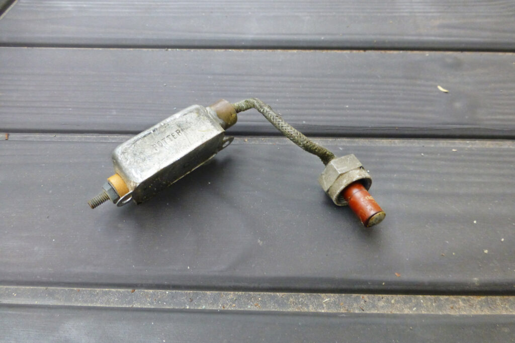
Those who know will know that that is a trick question. The correct answer is that the mag is on by default, which is part of the beauty of the device and why the engine will continue running even if you lose your other electrical power. The “P” (for Primary) lead goes from the ignition switch on the dash to the magneto where it is used to ground the Primary winding of the coil. When grounded, no field to collapse and no spark is generated. On the mags in this article, the P-lead goes to a noise filter (another capacitor) which has a fitting that goes inside the cover to touch a metal tab connected to the points.
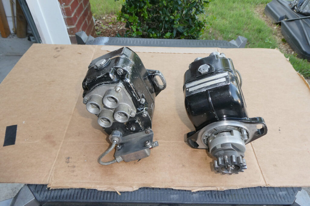
Practice over, I turned my attention to Mag1. Having completed the ground-use mag, assembling the main mag was very straight-forward, as was getting it internally timed. The new bearings made a huge difference in how it felt to spin when assembled, especially compared to Mag2. Placed on the bench and spun with a drill motor, the mag was generating strong sparks nearly a half inch long. Given the new coil, points, condenser, bearings, and seal, this one was rebuilt for something on the order of around $600. Both mags together were rebuilt for less than the price of a regular overhaul, and one of them is flight worthy as the backup to my eventual electronic ignition. Not too shabby.
Lessons learned
A major task in this effort is simply cleaning everything, the bulk of it being dried grease, dirt and old coil detritus. As it turns out, the new grease smells almost as bad as the old grease, and the old grease reeks.
The little clips that secure the coil wires to the case are not optional. Omit them and you’ll pinch the wires and short things out when assembling the case halves. Trust me on this.
If the bearing races had been too worn for use on the flight mag rotating magnet, I’d have had to purchase a suitable puller tool or take it somewhere.
Get a two-jaw pulley puller for removing the impulse fly-weights, and have patience about removing them.
The el-cheapo snap-ring pliers were made to work, but if you can find a slightly better pair, the little bit of extra spend will be worth it. The snap ring tended to want to twist during installation; a chopstick helped nudge it into place until the pliers were released.
Read and re-read the manual, and then consult it regularly during the rebuild to ensure that you don’t miss any steps.
Take plenty of photos as you disassemble; you will use them for reassembly
Do not throw away any of the parts during disassembly. You will reuse most of the them, and any that don’t get reused can be used as reference to make sure you get the correct new item.
Pay close attention to the details, especially when ordering replacement parts and making sure you are turning things in the correct direction.
If this type of work is within your wheelhouse, then by all means give it a try, especially for an experimental aircraft; if not, then send your mags to a rebuild shop. I had the luxury of multiple used mags from which to pick and choose parts—probably not a typical situation.
Likewise, I had the luxury of tinkering over the span of a month, including more than a week of soaking the armatures in penetrant whilst under tension to get the flyweights off. Per the manuals, I should have replaced both armatures, as they have been superseded, but again, experimental, so I used the ones I had, and they seem to work just fine.
As mentioned earlier in the article, I lucked out in that the bearing races on the flight armature were good enough to reuse, otherwise I’d have had to find a means pull them. I reused my two best looking gear wheels, one phenolic and one plastic, and the two best distributor blocks. A rebuild kit will have a new version of these two items. I also did not have the specified timing or test equipment for final bench testing, but again I’m not reinstalling directly onto a flightworthy aircraft. The drill-powered spark test appears to confirm that they are working correctly, but the proof will be on the engine test stand.
Epilogue 1
Both mags were taken to the build hangar and installed on the engine, with the flight mag going on the left side and the ground mag on the right. By the time we got them timed and the engine ready to go, we were at the end of the session. Fast forward to the next week’s build session and the flight mag wasn’t making any spark! Why?! How?! What on earth could have happened, sitting in a hangar, such that it quit working? I took both mags home to begin troubleshooting and was stymied for days. All components checked out individually, and the ground mag continued to work even after I swapped the coil, points, and condenser with the flight mag. It was maddening.
Finally the culprit revealed itself: it was the brand new carbon brush in the middle of the rotor: it was compressing down and getting stuck in the retracted position instead of extending up and contacting the coil. I had replaced the brush during the rebuild, so I’m at a loss as to why it was sticking.
Swapping the ground mag rotor to the flight mag made it operational. Whew! I went back to my collection of parts, grabbed another rotor, spiffed it up and installed it into the ground mag with the second new brush from the rebuild kit, and was rewarded with a nice spark when tested.
After using the ground mag rotor to get the flight mag working (and before I had a chance to finish the ground mag), I took the flight mag back to next build session, got it timed and connected it to the brand new spark plugs. We rolled the test stand outside, primed the cylinders, and commenced to converting fuel to noise. After a few more blades than I care to think about, the Lycoming roared to life and ran strongly until the carb bowl was empty! On just the one mag! Carb refilled with fuel, and it ran just as well a second time. The prop was removed and the engine returned to the hangar. The engine and stand were later trundled out for longer run times on a small gas tank, and both mags worked beautifully.
Epilogue 2
Eighteen months after this article was started and as I get closer to hanging the engine onto the firewall, I started some online shopping for electronic ignition and was taken aback by how much prices had increased since the last time I had priced them. Given that I have two working magnetos, I decided that they can both be used initially and that an electronic ignition could wait until my bank account had recovered from the other costs of getting the Thorp completed. With this decision made, I pulled the right-hand mag, the “ground only” one, to convert it to a non-impluse coupled version to match the shorter studs on the accessory case, plus replace the worn bearing races mention earlier. Um, easier said than done, as all of the armatures in the collection of parts are for impulse coupled mags. Seeing no easy way to convert the mag, I will instead pull the short studs from the back of the accessory case and install the longer studs needed for an impulse mag, leaving me as one of those builders with two impulse-coupled mags, at least until my bank account allows for adding electronic ignition.
![Careful planning and determination will get you to your goal of building and flying your own airplane. [Credit: AdobeStock]](https://www.kitplanes.com/wp-content/uploads/2026/05/Pulsar-Sunset.jpg?w=218&h=150&crop=1 "Last Bits")
![[Credit: AdobeStock]](https://www.kitplanes.com/wp-content/uploads/2026/05/AdobeStock_262642207_AGCuesta.jpg?w=218&h=150&crop=1 "Winging It")
![Lowell Farrand spent years serving as an FAA DAR and is in the EAA Hall of Fame. He offers sound advise to builders. [Credit: Bill Wilson]](https://www.kitplanes.com/wp-content/uploads/2026/05/unnamed-4.jpg?w=218&h=150&crop=1 "Think Like a Builder")
![Humberd and his daughter using the 701 for some farm duty transportation. [All Images Credited to Jon Humberd]](https://www.kitplanes.com/wp-content/uploads/2026/05/1-3.jpg?w=218&h=150&crop=1 "Builder’s Spotlight")
![[Credit: Viking Aircraft Engines]](https://www.kitplanes.com/wp-content/uploads/2026/04/engine.jpg?w=218&h=150&crop=1 "Editor’s Log")
![Author Bill Wilson takes a break from measuring and cutting the Lexan windshield during his Onex build. [All Images Credit to Bill Wilson]](https://www.kitplanes.com/wp-content/uploads/2026/04/image-2.jpg?w=218&h=150&crop=1 "Think Like A Builder")
![Andrew bought a Thorp T-18 project, which started him down the road to experimental aircraft project ownership and construction. [Credit: Andrew Robinson]](https://www.kitplanes.com/wp-content/uploads/2026/04/IMG_7725-scaled.jpeg?w=218&h=150&crop=1 "Winging It")
![The integrated ECLIPSE NG features a very sunlight readable display that shows the engine and all flight data organized in one or more pages. [Credit: Fielden Aero LLC]](https://www.kitplanes.com/wp-content/uploads/2026/04/1_Screenshot_.jpg?w=218&h=150&crop=1 "FLYBOX Avionics")
![[Credit: Chat GPT]](https://www.kitplanes.com/wp-content/uploads/2026/04/Generated-image.jpg?w=218&h=150&crop=1 "Homebuilder’s Insurance")


In your opinion what is the optimum product then for my RV6A Lyc o360/180A1A if one wanted to upgrade from standard magnetos to electric ignition ?
This is something of a personal preference and outside of my scope to answer. For instance: do you want a system that is self-energizing (like a traditional mag) or that requires a battery? For most people, needing a battery means having a backup battery in case something happens to the primary one, and wiring that accommodates circuit isolation and fail-over. Also, most of the electronic ignitions that I know of require adapter inserts for automotive spark plugs and new plug wires (typically a bonus given the price difference between automotive and aircraft sparkplugs). One exception would be Champion’s (forthcoming) electronic mag which is intended to be a drop-in replacement for the existing analog mag.
My advice would be to get on the forums, especially the RV forums, to see what others have used and their experience with the various options, and which one suits your individual preferences and criteria.
Comments are closed.