![Humberd and his daughter using the 701 for some farm duty transportation. [All Images Credited to Jon Humberd]](https://www.kitplanes.com/wp-content/uploads/2026/05/1-3-1024x683.jpg)
The question: Which build is currently getting more attention, the 750SDXtreme or the Super701/half? While the endless studying, drawing, calculating, designing, and waiting on several parts and components for the 750SDXtreme continues, as well as getting some local flying time behind the stick in another light and nimble 701, I have been focusing a little more on the very custom, and much more extreme Super701/half.
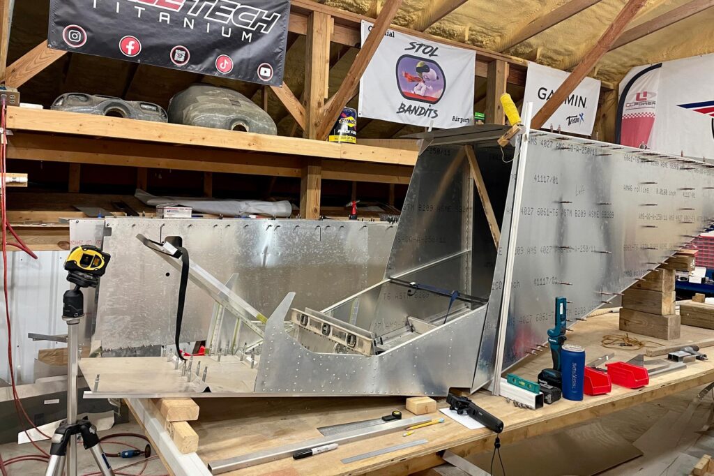
As mentioned previously, the first pieces of the titanium cabin frame are now fabricated and ready for mock-ups. The forward and rear fuselage of the Super701/half are also back on the build table and it is time to join these two main components of the airframe. Admittedly, I have been putting this particular step off, partially because I remember how time consuming it can be to get it “just right”, but now it is time to jump headfirst into this tedious task. The joining of this custom fuselage is something that needs to be as close to perfect as possible because it is the base for practically every other component that gets attached to the airplane. So here I am, chasing perfection.
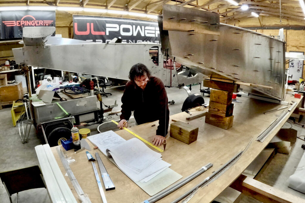
To get started with all of this, the rear fuselage has to be leveled in both directions, and it has to be square. I am basically using all the layout tools that I own for this. Several levels, measuring tapes, plumb bobs, a string level, a laser level, rulers, squares, and even an angle finder to double check all the specs I can come up with. The cabin sides have extruded aluminum angles that mate into the rear fuselage and these are a big part of the structural integrity of the fuselage with the finished airplane. In the 701 kits that were made before the current CNC final-hole-size match-drilled parts and components, the fuselage side angles had to be trimmed to fit by the builder during assembly. You definitely don’t want to get these extrusions trimmed wrong because they are mounted to the cabin sides with solid rivets that have already been pressed and assembled at the factory. Fitting these up to the rear fuselage requires many mock-ups, fitting, marking, taking apart, trimming, and then repeating, over and over. I am kind of glad this is a smaller, narrower, and lighter build (making it easier to handle) because I have literally installed and removed the forward fuselage to the rear fuselage at least 100 times at this point.
Once it finally fit to my satisfaction with everything being checked and double checked, all the holes have to be laid out with the proper edge distance and spacing, and each one drilled and clecoed for the final mock-up. Most of this Super701/half was ordered as the older style 701 kit, but also custom ordered on top of that, with many of the parts being completely undrilled, such as the fuselage skins and other pieces that would obviously be cut very differently than the standard 701 which is both longer and bigger than this highly modified build. There is a lot of time consumption with all the figuring and engineering to make this come together correctly, especially when modifying and cutting pieces to work with a narrower and shorter fuselage.
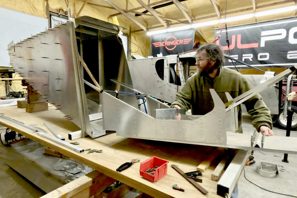
Now that I finally have the forward and rear fuselage joined, I can move on to adding more of the parts around the cabin, both above and below the freshly fitted cabin side angles. I have already installed some of these pieces and several are quite simple. The vertical side channels behind the doors are standard 701 parts. The heavier top channel, which is also the main carry-through for the rear spar attachment of the wings, was also ordered as standard, however it had to be cut down over a foot to fit up with the narrowed fuselage. I know there are a couple of single seat Zenith 701’s in existence, but I think they were only modified with the seat and controls within a standard 701. So this could be the first narrow body single-seat 701, meaning it will really be quite a prototype.
My thought process for the narrowed fuselage has two primary potential benefits. The first one is reducing the frontal area (drag), making it more streamlined and easier for the thrust airflow to get around the fuselage. The second is the weight reduction of all the trimmed pieces that are required to make it come together. Hopefully the combination of these two things will show some reasonable gains in performance. Although I have to remind myself that expectations are sometimes significantly better than reality and that the standard Zenith CH701 is already a lightweight and high-performing STOL airplane design as-is, so all this extra work may not show a huge loss of weight or significant gains in performance. The narrowed fuselage also creates several obstacles that take a lot of consideration and work.
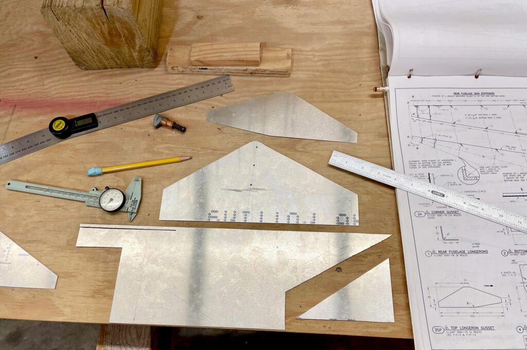
Once the channels were all installed on the rear fuselage, I was ready to work on fabricating new top longeron gussets. I looked carefully at the standard gussets and the blueprints, and the factory-cut gussets simply will not work for two reasons:
First, the angle between the top cabin tubes and the rear fuselage sides is less because the aft end of the fuselage remains the standard width (in order to fit the 701 tail), but the front of the rear fuselage is narrower, and this creates a different angle.
The second reason is because of the longerons I decided to use in this build. These longerons move the rivet line one edge over quite a bit from the rivet line on the standard longeron gusset, so now the gusset is a different shape and size. Let me explain… The standard 701 uses very simply formed L-shaped longerons that are two pieces overlapping in the middle and are installed on the outside of the fuselage skins. This design has worked very well for decades. However, I decided to use the 750 style longerons, which are a single piece from front to back and are a specially extruded and very robust structure that also includes a slight recess for the side skins. This allows them to be installed on the inside of the skins which gives the airplane a slightly more streamlined and finished look.
This is one of the few places in this Super701/half build where I decided to add a little extra weight, and lots more structural robustness. I don’t think this is really needed, but when I started on this project, I was contemplating building it as a tail dragger instead of a nosewheel airplane which would have put a lot more abuse on the rear fuselage. My opinion is that tail draggers look cool, but offer very little performance or STOL benefits over the robust Zenith nosewheel design. I even measured the possible max AOA (angle of attack) of these two variations—tailwheel vs nosewheel—while on the ground. My conclusion: when the tail is on the ground with both configurations on the same 701 airframe, the nosewheel version has the advantage of more AOA. This Super701/half will ultimately allow even more AOA on the ground because the rear fuselage is shorter, which moves the tail skid area forward while also creating a greater angle away from the ground on the bottom rear skin leading up to the rudder.
Anyway, back to making the new longeron gussets. I found a piece of scrap 6061 aluminum that was just big enough to make the two new modified gussets. After a little time planning them with careful measuring, cutting them to the rough dimension, then laying out and drilling rivet lines, I now have the required longeron gussets clecoed to the rear fuselage. They are only rough cut for now to allow any adjustments I need to make and will be trimmed nicely later on. These gussets will be important very soon with mocking up the rest of the titanium cabin frame.
As I continue adding pieces to the freshly joined fuselage, I come to more gussets that need to fit onto the cabin side angles (near the seat back). These gussets are slightly different from what the plans call for on a standard 701 as well, but luckily these particular gussets were supplied from Zenith as a bare rectangular piece of 6061 aluminum that had to be laid out and fabricated by the builder anyway, and these bare pieces were large enough to make them usable for this build. Even though this time it is pretty straightforward and quick to manufacture these pieces using hand tools, it makes me look over at the 750SDXtreme and think about how amazingly quickly the new CNC’d kits come together with finished parts that just cleco into place straight out of the box.
With the whole fuselage now lined up, leveled, clecoed, and mocked up on the build table, I am ready to start focusing on the titanium cabin frame again. The first pieces of this Tig welded frame can be clamped onto the cabin sides, but there is still a lot of work to get it ready for adding the cabin frame’s top tubes. There is a standard procedure that is described and shown very detailed in the Zenith 701 plans. It is a time-consuming order of operations to get it right, but basically you have to make wing pick-up templates using the wings as the foundation. I haven’t built the wings yet, so this is one area where doing things backwards is not very helpful.
The wings are needed to give you an accurate measurement between the main and rear wing spar attachments, which is then matched up on the fuselage by adjusting the upper tubes’ length on the cabin frame. The plans give you the goal measurement, but the older kits are ultimately one-off fitments because the builders had to lay out and drill many of the rivet lines by hand. There are lots of variations to how precise this is done by the builders, which is the primary reason for the required wing pick-up templates. However, with some thought and dedicated procedures, this can be done backwards, and the wings can be built to match the fuselage later on. A template is still required for both sides and the templates must be very accurate to ensure there is proper fitment and no binding or slack when the wings are installed. The template can be difficult to make perfectly when using hand tools because it has an angle on the front and the rear of the template that is not 90 degrees or even the same angle, so getting the final length of the template correct, while also ensuring the required angles remain accurate is a bit of a challenge. Kind of like the earlier forward cabin frame fitment, it takes a lot of back and forth with careful measuring, trimming, fitting, and repeating until it allows the correct and accurate positioning.
With the left- and right-wing pick-up templates ready to go, I can begin the next tedious process of using them to help mock up, level, and fit the first part of the titanium cabin frame by carefully trimming the titanium side tubes. At first you might think this should be an easy measure and cut fitment, but the template must hold the top of the cabin frame the correct distance from the rear fuselage all while everything remains level and squared up. This creates various angles between several tubes, longerons, gussets, and brackets that all need to come together as tightly and flawlessly as possible. So again, it is time to install, clamp, mark, remove, trim, and repeat until the titanium top and front tubes fit as accurately as possible.
Happily, I am beginning to see a lot of weight savings, especially when I look at all the trimmed off scrap pieces piling up. I really have no idea what the final weight might be or how significantly the modifications could help the performance, but I am hopeful.
There are still a lot of theories rolling around in my head that I want to try, but it can be both expensive and dangerous trying them all at once, and even more difficult to figure out which ideas truly help versus the ones that are a wasted or insignificant effort. The reality is that a lot of people make modifications to the Zenith airplane designs hoping for big improvements and they will almost always tell you that their modification makes a noticeable difference. With all the time and effort spent doing these modifications, they are going to be beneficial in our mind whether they really help in reality or not. Because it has to, right!?
This reminds me of the quote: “If the theory does not match the results, believe the results and change the theory”. Let’s just keep our fingers crossed that this custom build will all come together and ultimately work as flawlessly as possible!
![Careful planning and determination will get you to your goal of building and flying your own airplane. [Credit: AdobeStock]](https://www.kitplanes.com/wp-content/uploads/2026/05/Pulsar-Sunset.jpg?w=218&h=150&crop=1 "Last Bits")
![Making rare use of my drafting tools for the internal timing. [All Images Credited to Andrew Robinson]](https://www.kitplanes.com/wp-content/uploads/2026/05/P1010535.jpg?w=218&h=150&crop=1 "Conquering the Magneto, Part 2")
![[Credit: AdobeStock]](https://www.kitplanes.com/wp-content/uploads/2026/05/AdobeStock_262642207_AGCuesta.jpg?w=218&h=150&crop=1 "Winging It")
![Lowell Farrand spent years serving as an FAA DAR and is in the EAA Hall of Fame. He offers sound advise to builders. [Credit: Bill Wilson]](https://www.kitplanes.com/wp-content/uploads/2026/05/unnamed-4.jpg?w=218&h=150&crop=1 "Think Like a Builder")
![[Credit: Viking Aircraft Engines]](https://www.kitplanes.com/wp-content/uploads/2026/04/engine.jpg?w=218&h=150&crop=1 "Editor’s Log")
![Author Bill Wilson takes a break from measuring and cutting the Lexan windshield during his Onex build. [All Images Credit to Bill Wilson]](https://www.kitplanes.com/wp-content/uploads/2026/04/image-2.jpg?w=218&h=150&crop=1 "Think Like A Builder")
![Andrew bought a Thorp T-18 project, which started him down the road to experimental aircraft project ownership and construction. [Credit: Andrew Robinson]](https://www.kitplanes.com/wp-content/uploads/2026/04/IMG_7725-scaled.jpeg?w=218&h=150&crop=1 "Winging It")
![The integrated ECLIPSE NG features a very sunlight readable display that shows the engine and all flight data organized in one or more pages. [Credit: Fielden Aero LLC]](https://www.kitplanes.com/wp-content/uploads/2026/04/1_Screenshot_.jpg?w=218&h=150&crop=1 "FLYBOX Avionics")
![[Credit: Chat GPT]](https://www.kitplanes.com/wp-content/uploads/2026/04/Generated-image.jpg?w=218&h=150&crop=1 "Homebuilder’s Insurance")


