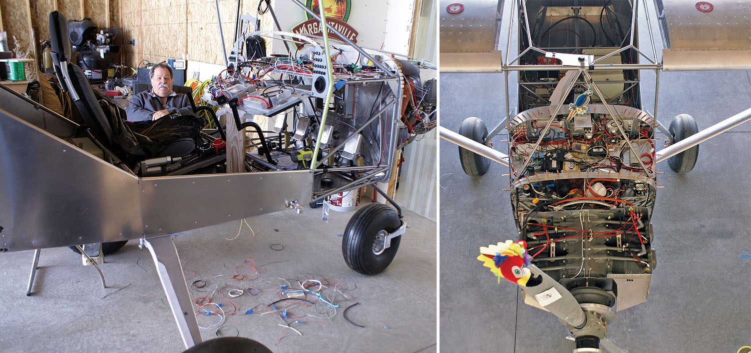
 Now that we have a fuselage sitting on its wheels, wings nearly complete, an engine hanging on the airframe and avionics for the instrument panel in place, it is time to forge ahead with the daunting task of wiring. I witnessed Mike doing the wiring for his previous project, a Van’s RV-10, and so I knew that it is a giant task. But to be into this project like I am and to know the complexities of the various systems that we have chosen was a rare treat and a real eye-opener. I know you can contract out the work (at a considerable price), but Mike was confident he has the knowledge, skills, supplies and tools to get the job done. Besides that, he seems to love the challenge.
Wiring is, to say the least, very complex. There are so many things to consider that are not obvious to the novice like me, such as fuses, circuit breakers, grounding, support systems and their wiring, and how it will fit in the space you have. The thing about Mike, which I have mentioned in other articles, is that he always has a creative plan to get the job done. The difficult thing about this for me is that it is all up in that head of his, and I have no idea what’s going on in there! During this process of building, I have learned that there is a time for instruction (him teaching me what the heck I am looking at), and there is a time to be quiet and let him think things through.
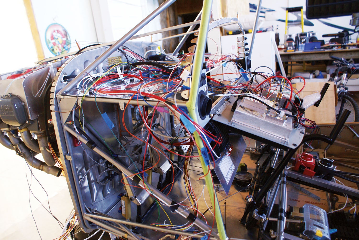
For the most part, wiring was a time to give him the space he needed to wrestle with the complexities of how this part of the project was to come together. I had no idea that it would take the many months that it did. I knew Mike was making progress, but visually it just seemed to pretty much look the same to me, which was a bunch of spaghetti wires going every which way that didn’t seem to make much sense.
Grounded Education
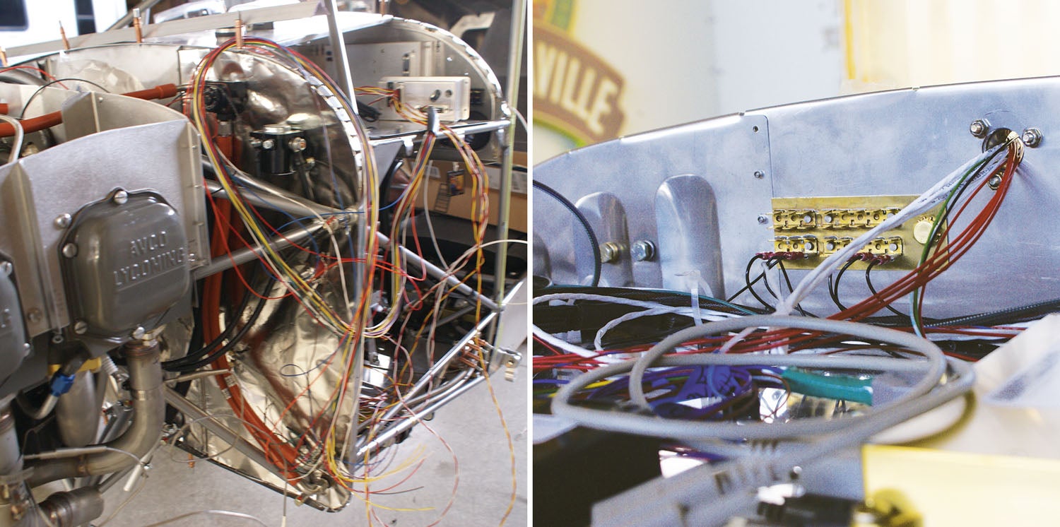
I did learn about the concept that every set of wires needs to have a ground. In the first place, it seems like a total oxymoron to talk about “grounding” in an aircraft. Still, when you get past that and grasp the concept that the electrical system needs to have a tie to the airframe to complete the circuit’s ground side, it seems to make sense. I just never realized until seeing what he was doing that each set of wires he was installing also had to have a ground to it. The grounds needed to be to a common location to keep many of the little boxes of electronics happy. There is a lot more involved than I realized.
In a similar vein, the concept of fuses and circuit breakers has always been a bit of a mystery to me. Mike took time to teach me about the need for each and which systems are best to be protected by a fuse or breaker. It’s up to you to choose fuses or breakers to protect your wiring/circuit from damage. With a fuse, you do not want to be replacing one in flight, and therefore the circuit protected by a fuse should be for non-flight-critical circuits such as lighting, power outlets and autopilot. Circuit breakers are used for more essential flight items such as radios and flight instruments.
It Takes a System
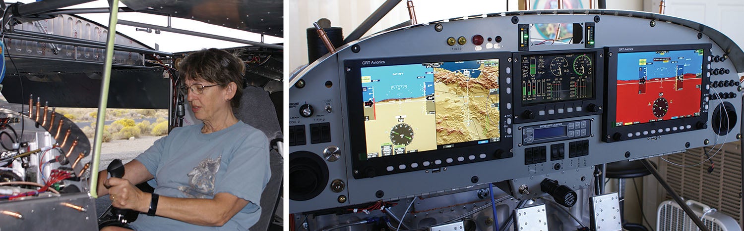
Mike had a systematic way of attacking the wiring of the instrument panel—see “Wiring Philosophy 101,” below. Mike took the time to show me the schematic sent with the EFIS from GRT Avionics. The thing that I like about wiring is that it is logical. You have a certain color wire that attaches from point X to point Y. Sounds easy, right? After multiplying that X to Y hundreds of times, it becomes pretty hairy, to say the least. I was able to track what Mike was doing part of the time and ask questions when he was not deep into cogitation mode to assist with my learning. It just seemed to take so long, and I wanted it to be right. One of Mike’s tactics was to get one instrument at a time “hooked up” electrically, then test it out to see if it was getting power and lighting up, even with the limited functions available—and without letting any of the “magic smoke” out.
One complication of our dual-EFIS installation is that we wanted to have the same information available to each screen yet have each display work independently. This required an Ethernet cable connecting the two units, which cut down on the wiring because each unit did not need to be independently wired. It was so exciting to see these units light up the first time.
When you fly the plane, you take so much for granted. You assume when you turn the key, the prop will turn over and the engine will start. When talking on the radio, it just happens. When you fly at night, you have wingtip and landing lights. These are all outside the core systems, like keeping the instrument panel working and the electronic ignition powered. But they all work together and integration is important. I’ll let Mike talk more about the peripheral wiring needed to make all the magic come together in “Backward Compatible,” below.
Department of Redundancy Department
Mike designed the electrical system with redundancy in mind because we do not have magnetos. I alluded to this in a prior article, but this is the time for Mike to describe his electrical system design for our S-21 in more detail—see “Nuckolling Down,” sidebar below.
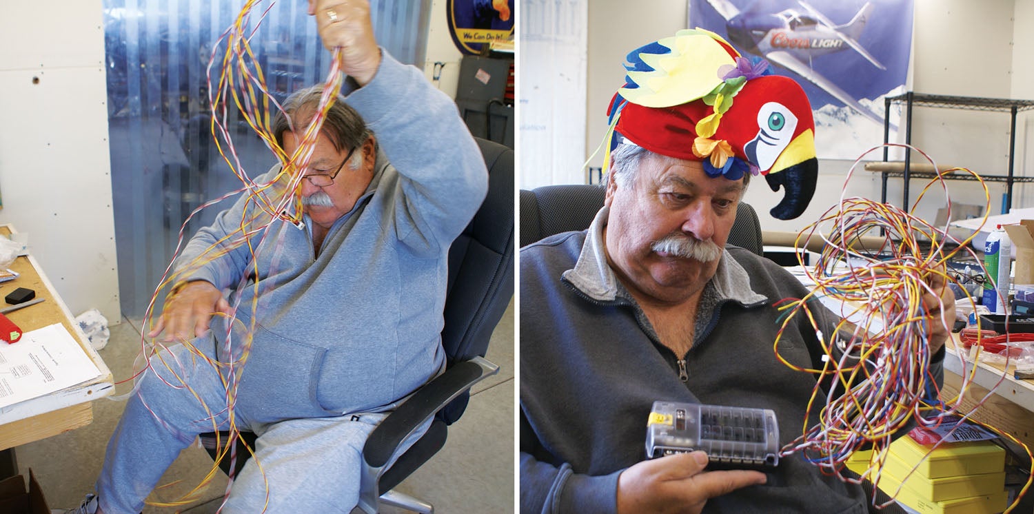
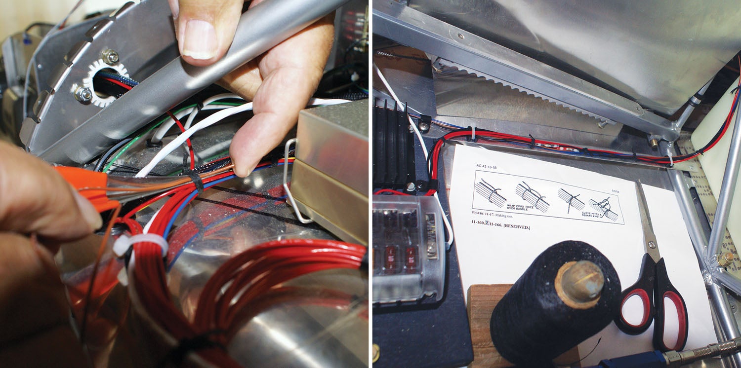
Throughout this whole process, it was a bit frustrating for me to figure out where I could contribute. Mike and our neighbor Paul discussed this one evening and concluded that wire lacing would be a great “Laura job.” I had no idea what it was, but it sounded like organizing and cleaning up the wiring in a way that I could handle. Mike had this cool little diagram of steps involved in how to tie the lacing knot. It took some practice, but I got it down and things wrapped together and cleaned up so nicely! Mike had zip ties around some areas that I was able to lace together. He finally could point me in the right direction, let me know what he wanted tied, and I could go for it. The lacing was a job for little hands and some patience. It came out so nice!
Mike had me do the lacing in areas where he was done. As it turns out, “done” can change! There was this time (I’m sure there was more than once) when Mike had to add an additional wire to where I had just finished lacing, and I was not too happy. I figured I would have to rip out the lacing I had just completed and redo it after he was finally done. As it turns out, he had this cool tool that you insert the wire into that acts like a little shoehorn and you can just pull the wire through the lacing! The wire spoon saved me from cutting and replacing the lacing several times, but I will warn you that the tip is sharp.
With the wiring nearing completion and fewer bundles for me to lace up, it was clear we had arrived at an important point in the project: riveting on the boot cowl. Why? Because the boot cowl, a structural piece, covers up the access to much of the wiring between the instrument panel and engine that lies on the shelf. Leaving it off creates much better access to the back of the panel, but it had to be installed sooner or later. It took a while before Mike was comfortable enough to take this final step, but it did finally occur! I was super excited to rivet the boot cowl on because that marked one of the final chapters in the wiring saga.


I would like to know what oil filter adapter you ended up going with ? I am installing an O-320 D3G in my S-21.
Comments are closed.