Last month we looked at how the static stability of the airplane when it is sitting at rest on its landing gear affects the position of the landing gear legs. Once the airplane is in motion, there are additional considerations that come into play. We will now turn our attention to how dynamic effects dictate the configuration for the gear.
When the airplane is sitting static on the gear, the forces are very simple. The weight of the airplane acts vertically downwards through the center of gravity (CG), and the reaction forces on the wheels act straight up through the centroid of the contact patch of each landing gear tire.
Accelerations, either due to braking or turning, also introduce inertial forces that act through the CG.
The interactions of these forces affect the behavior of the airplane and add several considerations to the proper placement of the landing gear.
Lateral Stability
As we saw last month, the contact points of the three wheels of the landing gear form the vertices of a triangle called the “triangle of support.” For the airplane to be stable on the ground, the force vector representing the sum of all of the forces acting through the CG of the airplane must pass through the triangle of support. When the airplane is static, this is simple. The CG of the airplane in the plan view of the airplane must fall inside the triangle.
When the airplane is in motion and turning, the force picture changes. The reaction forces on the wheels push sideways, into the turn. As a result, an inertial force having the same value as the wheel side force acts through the CG in a direction to the outside of the turn. This pair of equal/opposite forces produces a rolling moment to the outside of the turn. This causes the resultant force vector to tilt outboard. At some point, if the turn is sharp enough and the wheels have enough traction, the force vector will move outside the triangle of support and the airplane will tip over sideways.
The width of the landing gear measured between the main wheels is set by the need to have sufficient lateral stability for maneuvering on the ground. What is critical is the “tip-over angle,” which is the angle (in front view) of a line between the CG and the contact point of the main wheel. This angle determines the lateral G-force the airplane can sustain in cornering before it tips.
The height of the gear is typically set by other considerations such as propeller clearance or tail-strike on takeoff. Accordingly, the designer must first set the height of the gear and then choose the gear width needed to provide a large enough tip-over angle. The taller the gear, the wider it must be for a given tip-over angle. This can have significant effects on the weight of the landing gear, its drag, and where it can fit into the airplane if it is retractable.
On a high-wing configuration the main gear usually attaches to the fuselage directly. In this case the only way to increase gear width is to make the landing gear legs longer. This will make them heavier and increase drag if the gear is fixed.

Directional Stability
Having a large enough tip-over angle ensures that the airplane is unlikely to roll over when operating on the ground. This is not the only ground stability criterion we need to pay attention to.
When the airplane is rolling on the ground, the pilot must be able to steer it and, particularly during takeoff and landing, be able to keep it rolling in a straight line. To do this successfully, the pilot needs an acceptable combination of directional stability and steering authority.
Steering on the ground is accomplished using some combination of wheel steering on the landing gear (tri-gear or tailwheel), the rudder, and differential braking of the main wheels. Not all airplanes have all three available. For example, an airplane with a castoring nose- or tailwheel has no direct wheel steering available and must rely on just the rudder and brakes. An even more extreme case is the Ercoupe, which has neither separate rudder control or differential braking and relies entirely on nosewheel steering on the ground.
The directional stability of the airplane on the ground is primarily a function of the position of the main wheels relative to the CG.
When the airplane is rolling on the ground, most of the weight is carried by the main gear wheels. Accordingly, it is most illustrative to consider the case where the third wheel (nose or tail) is free-castering and cannot produce any side force. (While this is not strictly the case for many airplanes, the stability effects we are about to discuss hold true even if the third wheel can be steered.)
Forces
As we have seen above, in a turn on the ground, the main wheels exert a side force into the turn, and an equal and opposite inertial force acts through the CG toward the outside of the turn. If we consider these two forces from the top view of the airplane, we can see that they produce a yawing moment on the airplane.
If the main gear is ahead of the CG (taildragger), the yawing moment acts in the same direction as the turn and causes the turn to tighten. The pilot must actively steer the airplane all the time it is in motion to keep its path from diverging. If the airplane is going fast enough and the turn rate builds up enough, it’s quite possible for the inertial yawing moment to exceed the maximum steering capability available from the rudder, brakes, and tailwheel. In this case (the dreaded ground loop), the airplane’s path will diverge into a tightening spiral until it either stops, skids sideways, hits something, or tips over. This is at best embarrassing, and at worst catastrophic depending on how the divergent path ends.
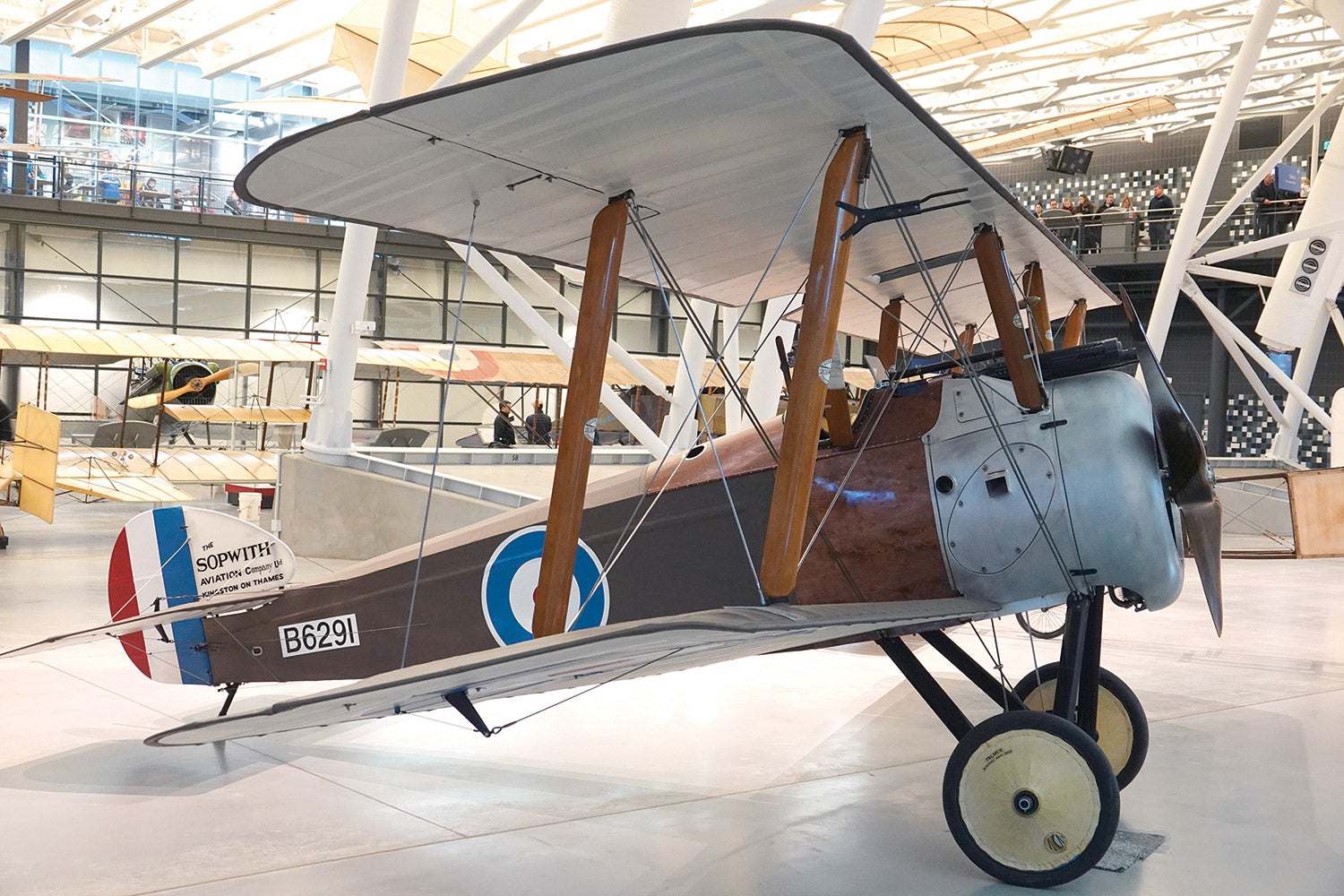
Early airplanes that operated off grass fields had tail skids that provided stabilizing drag on the aft end of the fuselage when they were in contact with the ground (Stick back!), which made the directional control issue workable even for airplanes with no brakes like most WW-I fighters. This approach does not work on smooth paved runways, so tailwheels were introduced. Some airplanes, particularly larger ones, had lockable tail wheels that could be locked in the fore and aft position to help with directional stability on takeoff, and most modern taildraggers have steerable tailwheels. In spite of these measures, the amount of side force a tailwheel can generate is small because it is lightly loaded, and if the turn rate gets very high, the tailwheel will skid and cease to be helpful in keeping the airplane straight.
Taildragging landing gear has significant advantages, particularly for fixed-gear airplanes, because it is lighter and lower drag than tricycle gear. It also provides better propeller protection for rough-field operations. But directional stability is the Achilles’ heel of the taildragger configuration.
If the main gear is behind the CG (tricycle gear), the yawing moment opposes the turn and tends to straighten the airplane out. If the nosewheel is free castering and the pilot does not use rudder or brakes to hold the airplane in the turn, it will straighten out and stop turning. This is stable behavior. As with tailwheels, nosewheels are lightly loaded, so in a tight turn the nosewheel will skid. Unlike the tailwheel situation, however, this is stabilizing since the turn will widen instead of tighten. In automotive terms, a trike gear has terminal understeer, while a taildragger has terminal oversteer.
The natural directional stability of the tricycle landing gear configuration is the primary reason it has become the predominant landing gear configuration for the vast majority of airplanes designed and produced since WW-II. In spite of its higher weight (and drag for fixed-gear airplanes), the stability and ease of operation of the tricycle gear arrangement outweigh the other advantages of the taildragger configuration for most missions.


