 Retrofit standalone engine and fuel monitors soldier on, serving panels not yet upgraded to a primary EFIS. Straight up, we think an entry-level EFIS with a built-in engine and fuel interface is money better spent. (For a primer on EFIS features see “Big Screen EFIS Buyer’s Guide,” June 2022.)
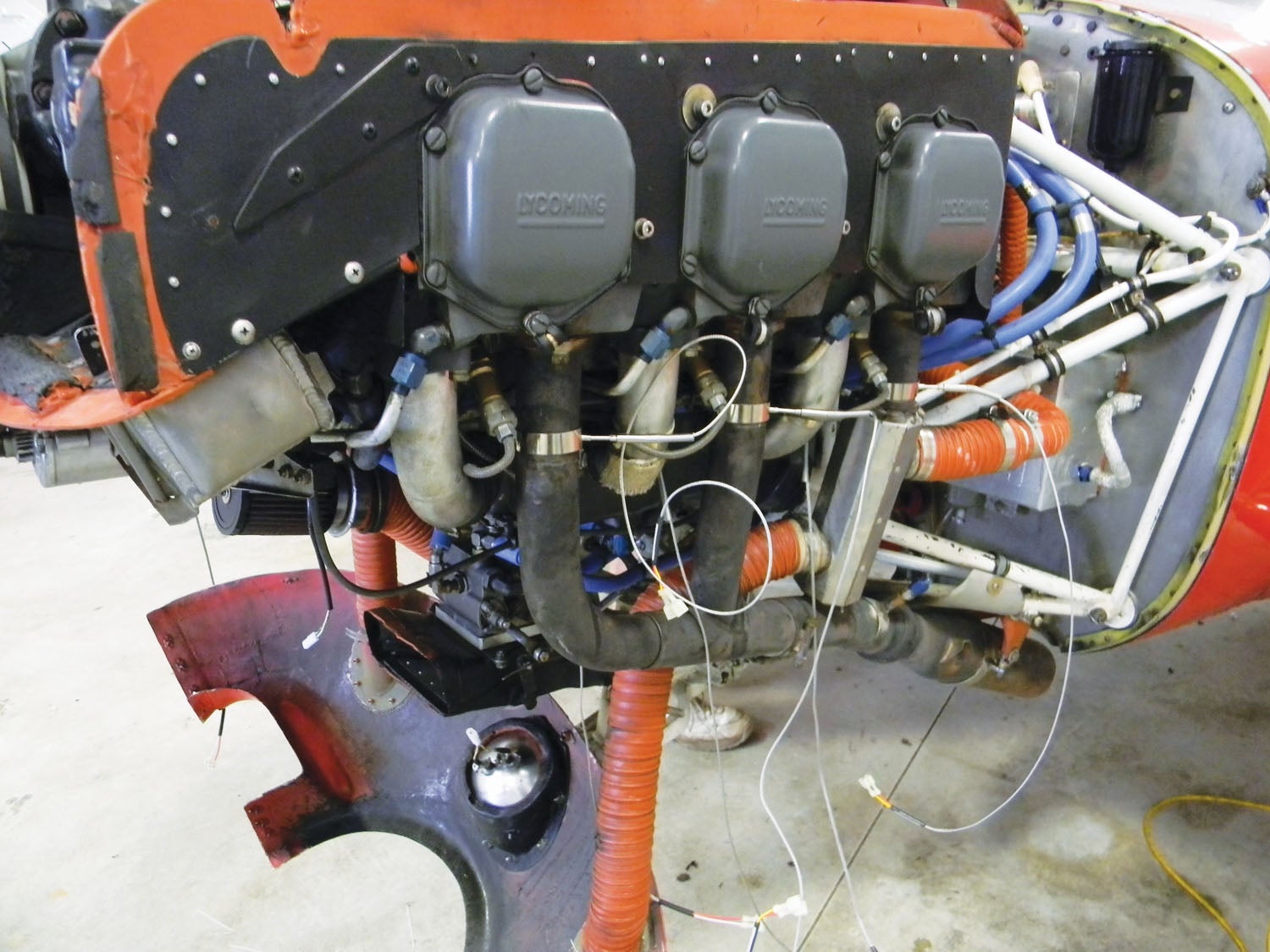
![]() No matter what you choose, nailing the complex installation is critical to performance and safety. Here we’ll scan the market for standalone monitors, where little has changed (except a worsening supply chain) since we last looked at them in August 2020. This time we’ll focus more on installation tips and traps to avoid when you’re putting these systems in. Let’s start with the easy part—the metal work.
No matter what you choose, nailing the complex installation is critical to performance and safety. Here we’ll scan the market for standalone monitors, where little has changed (except a worsening supply chain) since we last looked at them in August 2020. This time we’ll focus more on installation tips and traps to avoid when you’re putting these systems in. Let’s start with the easy part—the metal work.
Physical Installation
A good engine monitor installation starts with a healthy dose of planning, and that means finding the best spot on the panel to house the control head. There may not be many good options without moving stuff around—which could be worth the effort. Think about it: A monitor that’s placed outside of your primary scan (especially ones with smaller LCD displays) could mean missing critical warnings and alerts because these are interactive systems. Do you really want to be reaching across the panel to get to it? The pilot’s instrument panel is generally the best spot, especially if the unit has fuel flow and even fuel quantity functions. The center radio stack might work too, but we would keep it up high, leaving enough space behind the panel to access and work with the mating connectors. Most systems have audio outputs for streaming alerts into audio systems—a worthwhile interface and good reason for an audio upgrade while things are taken apart.
For existing kits still sporting round-gauge flight instruments, installing the monitor in an existing instrument cutout is easiest because you might not have to make any panel cuts, and the display should be nicely placed so it gets your attention.
Electrical Installation
As with any installation, start with the most current version of the installation manual, and have available the engine maintenance manual. This may seem obvious, but we’ve fixed enough engine and fuel computer installations where it seems neither was available.
Start by deciding how the system will be circuit-protected. Use high-quality push/pull breakers (we favor Klixon) properly rated for the unit. We’ve seen some installations where the engine and fuel monitor were on the avionics bus, rather than on the primary bus where it’s almost always preferred.
Plan the harness installation. On either side of the firewall, properly secure wires that can chafe or vibrate and provide adequate service loops, separating small-signal wires from high-voltage wires. Bundling high-tension leads (ignition wires) along with the temperature probe thermocouple wires causes induced voltage into the thermocouple wires because of the EMF (electromagnetic field) created by the high voltage passing through the ignition harness. This results in rapid fluctuations in readings.
Also, if the drawing calls for shielded wire, use shielded wire. Keep in mind that some sensors (including critical flow transducers) are susceptible to electronic noise, and shielded wire will improve their performance. Carefully follow the install manual guidance on which end of the shield to terminate (i.e., connect to backshell).
One common trap with Garmin’s EIS (Engine Instrument System), as well as with standalone monitors, is not grounding the engine case to the same ground point as the engine monitor. This ground strap is essential for good electrical performance of the sensors. You can ground all the sensors to the engine, but if the engine is still isolated from the avionics ground by the rubber mounts, it’s simply not a good ground.
Paul Stanczyk, a support engineer at JP Instruments, pointed out that one common error on metal airframes is thinking you have a complete circuit by grounding anywhere on the airframe. Because it’s an all-metal aircraft and an airframe ground was made somewhere else (maybe behind the instrument panel), the ground becomes a “floating ground.”
“When installers check a fuse or circuit breaker (or the ‘hot’ line to a device) they use a light tester or multimeter. One side of the light tester or multimeter is grounded somewhere on the airframe close to the wire being checked for ‘hot.’ Think about all those individual pieces of metal in between the airframe ground at the panel and the ground on the device you are checking for power. In flight the airframe is moving, and that ground near the device goes the shortest route it can find to the source ground at the panel. As you fly, the many pieces move and a shorter path may occur, which changes the amount of resistance in the circuit and thus the voltage,” Stanczyk explained.
JPI uses “K” type or what is referred to as grounded probes. These are faster than “J” type or ungrounded probes. Because of this, it is preferred that the engine data management system (EDM) is grounded at the engine block on the case-half spine through-bolt. The accessory drive case works most of the time; however, there are those times it doesn’t.
Back to the floating ground issue behind the panel: Think of the points of contact that the ground has to make going back to the engine; each contact point on the ground side has a voltage drop potential that can add up fast, which causes errors in the readings.
Stanczyk also had some good advice for making connections with fuel senders. Here, the floating ground issue is critical. He sees a lot of amateur installers taking shortcuts and not going all the way out to the sender with the ground wire of the EDM’s P6 harness. You might run into problems during fuel quantity calibration where the output value is changing constantly due to the ground being put on the wing root instead of going all the way to the sender. This is even more problematic when utilizing the highly accurate CIES digital senders.
“You are talking about measuring millivolts from the senders. In the case of CIES frequency senders, a direct connection to the ground wire of the sender to P6 harness is made,” he advised.
Sensor Installations: Beware of Engine Variations
Members of the Garmin Team X Experimental avionics engineering team had good advice for installers working with the EIS, and much of it holds true for any engine monitor install. Again, go deep in the manual and look specifically at the requirements for the particular sensor being installed. Installers often call the support line looking for specific “pin numbers” for wiring the external sensors to the EIS unit. Garmin warns that looking at the pin-out list in the manual is useful, but it does not tell the whole story about the requirements for each sensor or component.
A better source, according to Team X, is the interconnect diagram, which is a visual wiring diagram that shows the sensor and all of its associated wiring, so there’s no guesswork. And get your specific engine right—Garmin has sensor wiring examples for Lycoming, Continental, Rotax and Jabiru engines, with a drawing for UL Power FADEC as well. On a side note, in the early gen G3X engine monitor product, Garmin used high-density contact pins—notoriously difficult for amateurs to work with—but they’ve since been changed to standard-density pins. Garmin said that when making the transition to the newer system (it uses a different EIS module—the GEA 24), installers shouldn’t have to re-pin the entire system end to end.
As for individual probes and sensors, engine manufacturers will usually have guidance for physical installation of their required or recommended sensors. Thankfully, Garmin provides fairly detailed general guidance for installing sensors it sells in the G3X Touch installation manual. You’ll find it in Section 24, under the Engine/Airframe Sensor Installation subhead. There may be some flexibility to use third-party sensors. Many temperature probes (CHT, EGT and oil temp) are classified as a certain type of thermocouple, and even Garmin’s EIS will read any standard Type K or Type J probe for most applications. Also, the G3X works with several different brands of fuel flow indicators (Electronics International and FloScan, to name two). For new installations, Garmin’s kits will get you started for major items like EGT/CHT and pressure sensors, but you may have some probes that come with the engine or other probes that you source. They might work—but the manual is the final authority.
Dynon’s Michael Schofield said the company tries hard to make the install installer-proof. “We find that amateur builders are generally pretty good with our systems because we have color-coded harnesses that make wiring pretty simple. Generic mis-wires—or having a probe that isn’t wired even when the installer thinks it is—are probably the most common problems. Having the wrong sensor selected for a sensor channel ranks up there too,” he said.
“The SkyView ships with reasonable defaults, but people have unique needs. Calibrations, whether fuel level, flaps/trim or adjusting the K-factor for fuel flow/computer, are probably the other things that trip installers up,” Schofield told us. But that goes back to our point: Many of those issues would be solved if builders simply followed the manual.
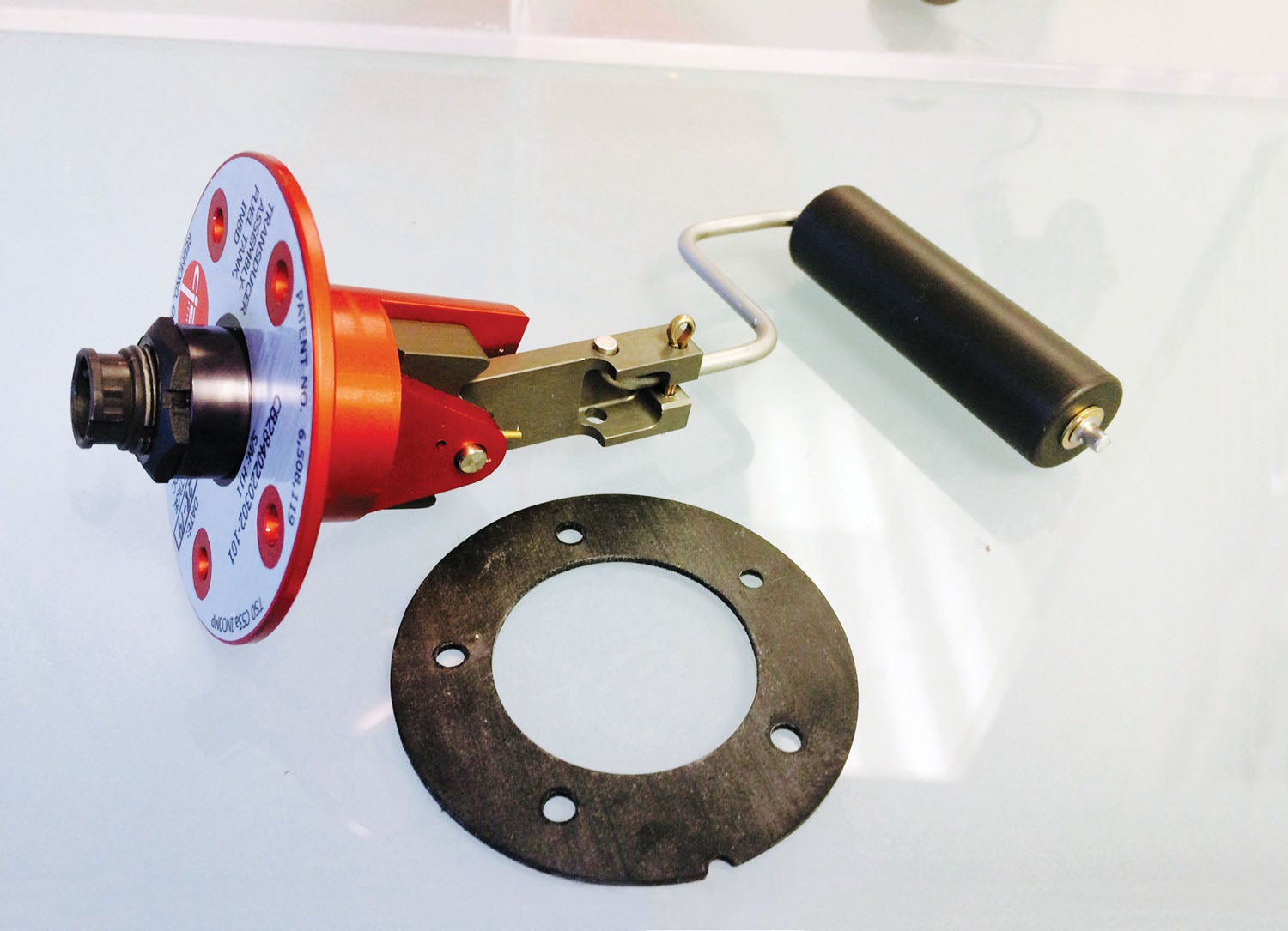
Critical Fuel Flow Interfacing
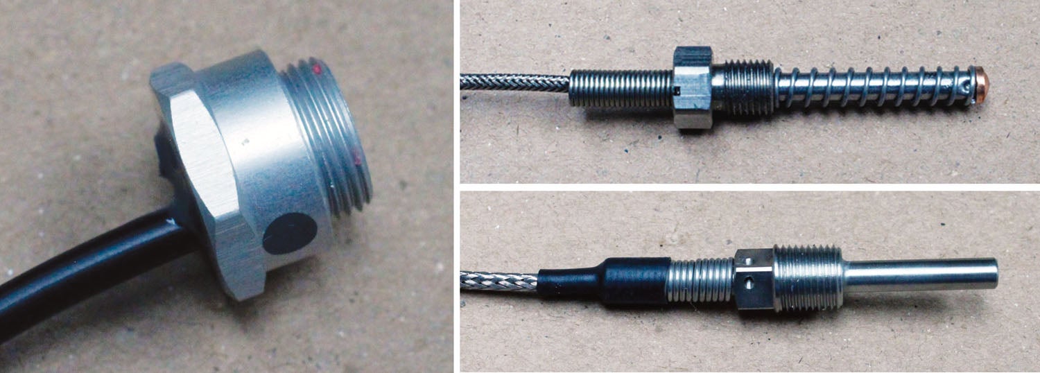
No matter which system or on which engine you’re installing it, pay close attention to the installation techniques when it comes to fuel flow transducers. Fuel flow is the amount of fuel that flows past a given point in the fuel system at any given time, usually depicted in gallons per hour. Fuel flow is measured by a fuel flow transducer—a device installed in the fuel line that’s essentially a turbine that converts to a digital signal using light optics.
Many fuel flow computers use common flow transducers, and one popular one used in a wide variety of fuel computers is made by FloScan. If your engine is equipped with a fuel return line from the carburetor back to the fuel tank, you will need to install two fuel flow transducers—one in the feed line from the fuel pump to the carburetor and one in the return line from the carburetor back to the fuel tank. This applies to certain Continental engines and Rotax 912 ULS and 914 engines.
Using Garmin’s fuel flow install as a general example, if there is a fuel return line, Garmin provides the necessary software and hardware interface to account for two fuel flow transducers. But this applies to most all systems; both transducers need to be installed in the aircraft per the fuel flow transducer manufacturer’s instructions. In general, the fuel flow transducer should be installed in a straight section of the line, and a distance of 6 inches on each side is desirable. It also needs to be installed downstream of a fuel filter in the engine bay and also not directly secured to the engine to avoid excessive vibration. And whatever you do, protect the transducer and the fittings by covering them in high-quality fire sleeve.
JPI sees plenty of fuel transducer installations gone bad, and its advice echoed Garmin’s Team X. Vibration is the enemy. You want to avoid “hard mounting” and “vertically mounting” the fuel flow transducer. The impeller inside rotates on jewels to allow a virtually friction-free rotation, and orientation is a requisite for longevity. You want to minimize vibration by “hanging” the transducer—or having a hose going into and a hose going out of the transducer.
It’s also worth mentioning that oil pressure and manifold pressure transducers generally don’t last long when exposed to vibration.
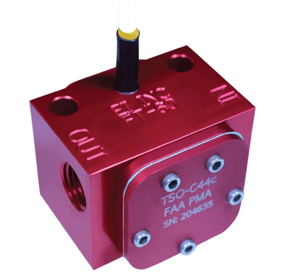
Electronics International says its Red Cube FT-60 fuel transducer has considerably less pressure drop than other units on the market, and a blocked rotor does not affect pressure drop. The overall accuracy and linearity of the Red Cube FT-60 is superior to most other flow transducers, too. The Red Cube FT-60’s design vacates bubbles and is not nearly as susceptible to debris as other units. Garmin says that EI’s transducers are used in some of its EIS applications.
Do not hard mount pressure sensors anywhere on the engine or cooling baffling. The best place for pressure transducers is on the firewall. Having a 90° bend ahead of the fuel flow transducer is also not recommended. The bend creates turbulence in the fuel, hence an inaccurate fuel total.
Fuel Quantity Is Not Fuel Flow
This seems simple enough, but some amateur installers simply can’t separate the two concepts. If the engine monitor has fuel quantity capability, you’ll either use the existing fuel tank senders or install aftermarket digital senders—generally recommended, even over having the old senders repaired or overhauled. We like the CIES digital senders.
We asked Garmin for some tips on getting the EIS fuel quantity function accurate out of the gate. Besides starting with known-accurate fuel senders, nail the calibration process. Two fuel calibration curves are supported: the standard flight-attitude calibration curve and an optional on-ground or ground/taxi attitude calibration curve. The ground/taxi calibration curve can be used for aircraft that have a significantly different attitude when on the ground, such as tailwheel aircraft. As you might expect given the nature of measuring the amount of fuel splashing around in the tanks, selecting the wrong attitude can be a time-consuming and frustrating mistake.
Worth mentioning is that the Garmin GEA 110 interface adapter really has only two ways of measuring a fuel quantity value: by being a voltmeter or by being a digital frequency counter. If you aren’t using something stone simple like standard float gauges, make sure you understand what your fuel quantity sensor is actually doing. Sometimes they will be marketed as “digital” but will actually output a 0–5V analog signal, as one example. Read the calibration section of the manual before you start.
Garmin says that float senders will hit the top of the tank before it’s full in most aircraft. Don’t fret about it—your tank will read full until a certain amount of fuel burns off, and this is normal. Over at JPI, its tech support knows what we have for years: Setting the K-factor is critical. The correct K-factor (the number is found written on the side of the transducer) must be inputted into the EDM. Each aircraft has a unique fuel system and may need adjustment or fine tuning of the K-factor. Stanczyk at JPI reminds us that the pilot’s guide has the formula to fine-tune the K-factor. You’ll likely need it. The chore usually consists of taking three flights and recording how much fuel you boarded after each flight and how much fuel the flow totalizer says you boarded.
Finally, if there’s any question about your ability to work with the aircraft/engine’s fuel system during the installation, we suggest lobbying the help of a mechanic or shop to backstop the work. We’ve seen ugly engine fires as a result of doing things the wrong way.
This completes our primer on how to install an engine/fuel monitor correctly. What follows is a summary of standout Experimental standalone systems.
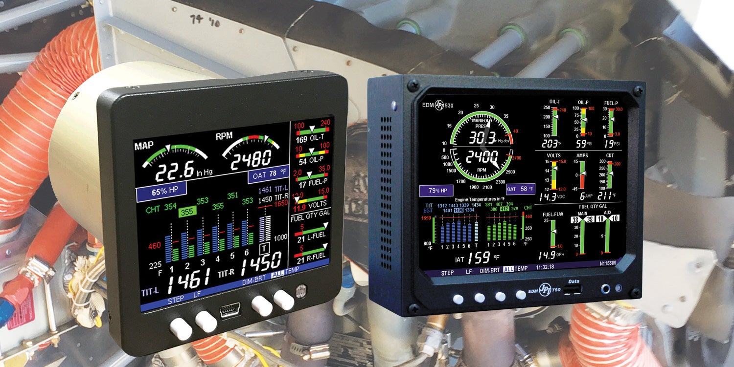
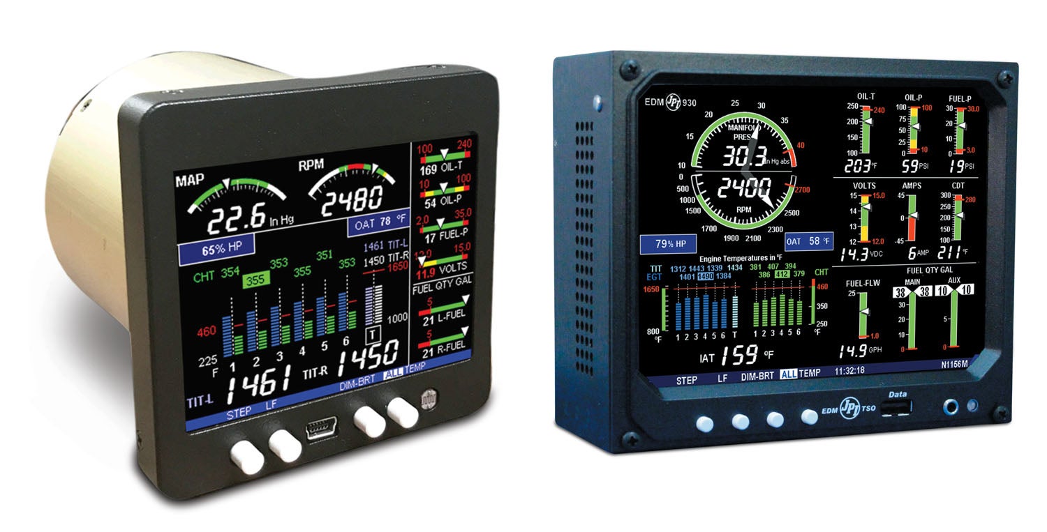
Electronics International
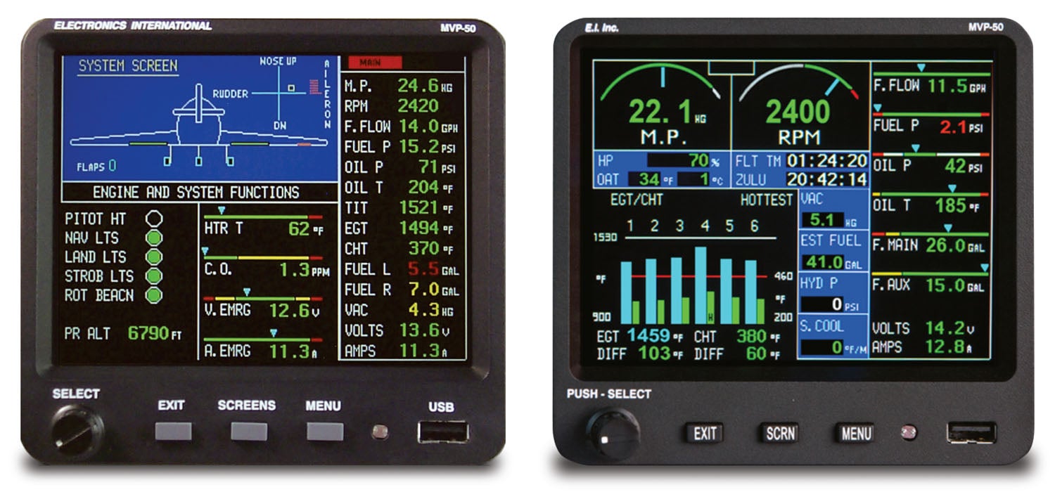
There are two specific models that are the most popular for Experimentals. One is the non-certified version of the big-screen MVP-50P.
As standalone monitors go, the MVP-50P is big—5.6 inches wide, 5.2 inches high and 2.4 inches deep—and mounts from behind the instrument panel, which means the TFT color screen sits flush. It isn’t a touchscreen. There are multiple components including MVP display, engine data converter (EDC-33P), the engine probes, transducers and modules, and the wiring and extension cables. The EDC is a smart box, converting raw probe and sensor inputs to serial data, which is then provided to the MVP-50P via two-wire RS-422.
This system is more than an engine and fuel monitor. Think of it as a systems monitor, with lots of data sprawled out on various pages. We especially like the System page and its ability to see the disposition of the landing gear (on retracs) and flaps configuration. As much as we like this system, we think it’s about time for an upgrade to touchscreen.
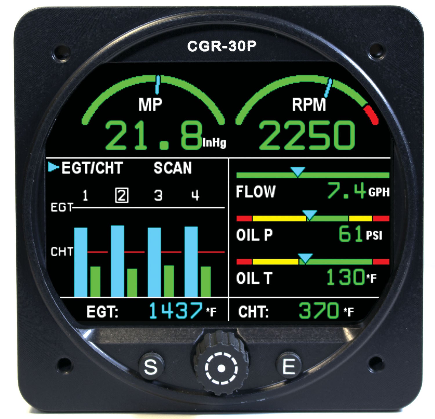
The EI CGR-30P is an easier install since it fits in a 3-1/8-inch instrument cutout. The system comes standard to display rpm, EGT/CHT bar graph, fuel remaining, tach time, local time, fuel used, GPS/fuel flow data, external caution and warning, and data recording. You can also choose five additional parameters from the list of manifold pressure, oil pressure, oil temperature, fuel flow, fuel pressure, fuel level (left and right tank), aux fuel level, TIT, carbon monoxide detector (a $495 option), vacuum and volts. The CGR also has a fuel totalizer and can monitor fuel quantity. It’s smart enough to know which fuel tank you are drawing from and can estimate how much fuel is remaining in each. A nifty on-screen graphic depicts the total fuel remaining in all tanks.
Taking the interface one step further, both the MVP and CGR can interface with the company’s AV-17 voice annunciation system. This remote system provides up to 17 verbal warnings through the headphones via the aircraft’s audio panel or compatible intercom.
Last, for the most basic all-in-one monitoring, EI has the bar-graph style UBG-16, which fits in a 2-1/4-inch instrument cutout. It has minimal user controls to cycle among three major displays modes: Normal, Normalized and Lean. There are a total of 16 input channels on the UBG. The columns of bars can display EGT, CHT, TIT or oil. Other functions will be indicated only in the digital display. While viewing the digital readout for the last column of bars, you push the Step switch to the right to display the next temperature or function connected to the UBG’s input channels. Bare-bones, but functional just the same.
flagship monitors. They have proven reliability and the sensors can be ordered to fit a wide variety of engines.
JP Instruments
In a recent interview, JP Instruments said the Experimental-focused EDM-350 represents only 5% to 10% of JPI sales and seems focused on the certified market. Still, at a time when other companies are backordered because of the chip shortage and JPI itself has some parts backorders, it’s shipping product on time.
The EDM-350 is a no-nonsense color monitor that fits a standard 3-1/8-inch instrument cutout and has a 3.5-inch square bezel. You can orient the display for a landscape or portrait view, and a simple bar graph and numeric readout for EGT and CHT is in the main area of the screen. When optioned, rpm and manifold pressure are at the top.
The 350 trickles down from the TSO-certified EDM-730 system. You can order it basic or in what JPI calls a full-featured model with a P5 connector that handles fuel quantity, fuel pressure and amps options. The base-model EDM-350 has EGT/CHT only and is priced at $1200 for four-cylinder engines and $1450 for six-cylinder installations. Simply add plug-and-play options, including rpm, manifold pressure and oil pressure ($299 for each), plus other options like the FloScan fuel flow transducer ($595 for carbureted and $490 for fuel-injected engines). There’s also a $95 remote warning annunciator.
Worth mentioning is the built-in diagnostic mode, which helps find sensor issues when the system boots. Any newly installed options are found and logged in at this time. If a probe problem is found, diagnostic indications will be presented on the display. The EDM compresses and records all displayed parameters once every 6 seconds in long-term data memory. (You can change this rate to be 2 to 500 seconds.) This data is retrievable by inserting a USB drive into the jack on the front of the instrument.
JPI still sells the EDM-930 Experimental—an all-in-one big-screen monitor with a price that tops $7000 with popular options. That’s tough to compete with an EFIS install, in our view. Still, it has a brilliant display with data that’s logically presented and customizable. The chassis fits in a 3-1/8-inch instrument cutout (it can also be flush mounted), but its large display bezel means it will occupy a lot of panel real estate that may be better served by an EFIS.
Grand Rapids EIS
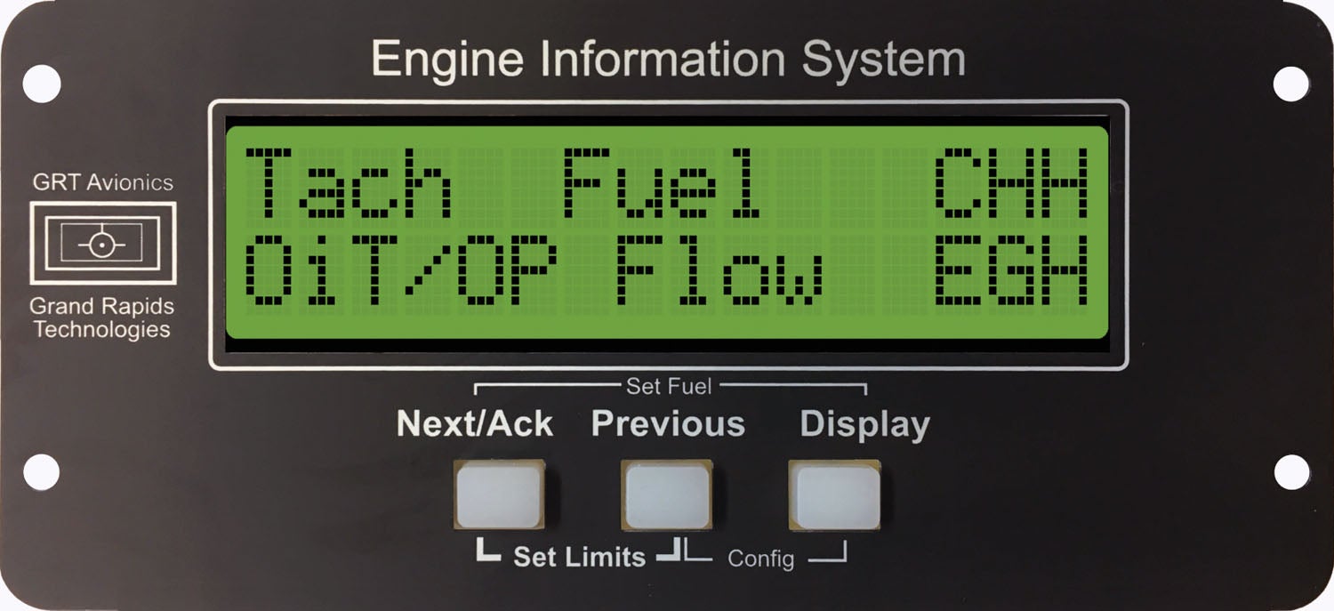
First, the Grand Rapids EIS. Think utilitarian. This system has been around since the 1990s and it shows, with its 32-character LCD display. Still, we like that it can remain in a Grand Rapids EFIS install as a secondary display. The EIS line includes the model 2000, 4000, 6000 and 9000 EIS (nomenclature corresponding to the number of cylinders), and each has five pages of scrollable data on a rectangular control head, which measures 5.9 inches wide, 2.8 inches tall and roughly 3.0 inches deep with electrical connector. The system has both engine data storage and download capability. The EIS can work well, even as a standalone fuel computer, when connecting a fuel flow transducer. The basic M4000 package for a four-cylinder Lycoming is $1295 and includes wiring harnesses, bayonet-style CHT probes and adapters, EGT probes, oil pressure sensor and oil temp sensor. For $1881 you get fuel flow and fuel pressure sensors, plus manifold pressure, while a remote EIS for EFIS connection is $1774.
MGL Xtreme EMS
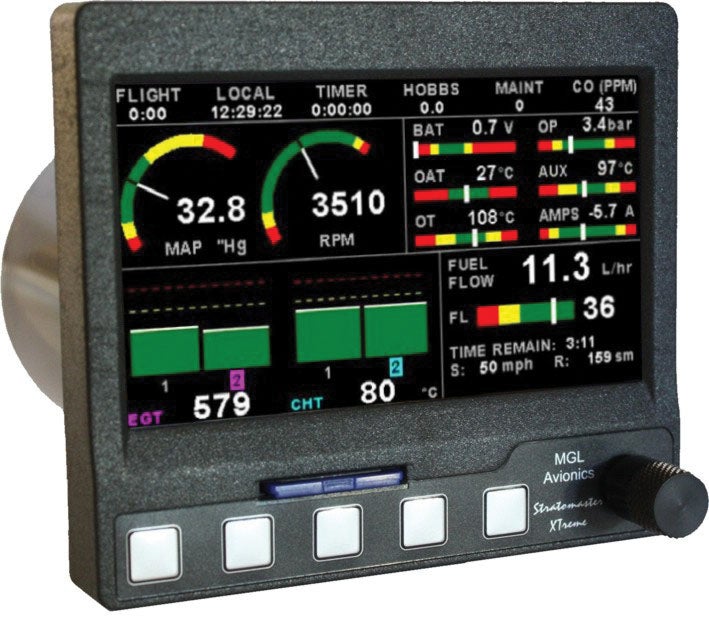
MGL’s Xtreme EMS is made to fit a 3-1/8-inch instrument cutout and has a 4.3-inch high-res color TFT LCD display. Installation is straightforward with a single D15 input connector on the rear chassis, and the system has provisions for a GPS input (for fuel endurance calculations).
The control set is focused around a rotary control knob and five bezel buttons, and the left- and right-most soft keys are used to cycle through the EMS pages. There’s a dedicated menu for adjusting the display backlighting on the fly, and it’s controlled with the rotary knob. Pretty simple.
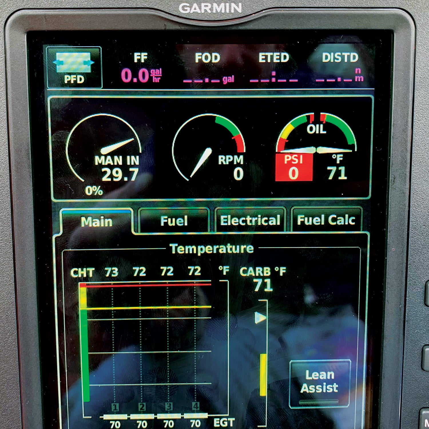
Garmin GI 275 EIS

While not an Experimental engine monitor, we think the Garmin GI 275 EIS (Engine Instrument System) is one worthy choice if you don’t want to cut metal. That’s because the GI 275 drops into an existing 3-1/8-inch instrument cutout. Keep in mind that a Garmin EIS is essentially the same whether it’s displayed on a G3X Touch (we suggest pricing this out) or on a small GI 275.
Engine, fuel and electrical data for the EIS goes through Garmin’s $745 GEA 24 engine interface module. The basic package with the GI 275 starts at $4495. But the common misunderstanding is that any GI 275 can function as an EIS. While the hardware may be the same, the software isn’t. This means that a GI 275 configured as a primary attitude instrument or electronic HSI/DG can’t function as an EIS.
Moreover, Garmin’s target audience for the GI 275 is buyers who want to replace each individual round-gauge instrument (in certified aircraft) with GI 275s—one of which might have EIS functionality. Think standalone engine and fuel monitor. And as such, it packs a big punch in a small chassis, including the Lean Assist, calculated percent power and exceedances alerting. Still, even the entry-level single-screen G3X Touch integrated avionics system is worth considering, given the added utility.
Wrap It Up
Two systems that made our last roundup—JPI’s EDM 740 and Dynon’s EMS-D10—have been discontinued, perhaps reinforcing that even the most basic EFIS options with built-in engine, fuel and electrical data are simply more popular.
If we had to pick a basic standalone monitor, it might be the Electronics International CGR-30P. We think it has an intuitive user interface, a good display and useful functions as standard.
Photos: Courtesy of the manufacturers.
| Model | Price w/ Basic 4-Cyl Lycoming Probe Pkg. | Display (in) |
Mount. Hole Dim (in) |
EGT/ CHT Chan. |
Engine Speed |
Man. Pres. |
Oil Pres. |
Oil Temp |
Fuel Flow |
Fuel Level |
Data Link |
Data Log |
|---|---|---|---|---|---|---|---|---|---|---|---|---|
| Electronics International | ||||||||||||
| CGR-30P Basic | $3,798 | 3.0 color |
3-1/8 | 4-6 | Y | Y | N | N | Y | N | RS-232 | Y |
| CGR-30P Premium | $4,598 | 3.0 color |
3-1/8 | 4-6 | Y | Y | Y | Y | Y | Y | RS-232 | Y |
| MVP-50P | $6,000 | 5.7 color |
5.5×5.1 x 2.4 |
4-6 | Y | Y | Y | Y | Y | Y | RS-232 | Y |
| UBG-16 | $1,698 | 2.0, LED | 2-1/4 | 4-6 | Y | Y | Y | Y | Y | Y | RS-232 | Y |
| Garmin | ||||||||||||
| GI 275 EIS | $4,830 | 3.0 color |
3-1/8 | 4-6 | Y | Y | Y | Y | Y | Y | RS-232 /CAN |
Y |
| Grand Rapids | ||||||||||||
| EIS | $1,295 | 2.0×3.0 dot matrix |
5.13×2.6 | 2-9 | Y | Y | Y | Y | Y | Y | RS-232 | Y |
| JP Instruments | ||||||||||||
| EDM-350 | $1,200 | 3.0 color |
3-1/8 | 4-6 | Opt | Opt | Opt | Opt | Opt | Opt | RS-232 | Y |
| EDM-930 | $6,100 | 5.0 color |
6×4.5 | 4-6 | Y | Y | Y | Y | Y | Y | RS-232 | Y |
| MGL Avionics | ||||||||||||
| Xtreme EMS | $1,820 | 4.3 color |
3-1/8 | 4-6 | Y | Y | Y | Y | Y | Y | RS-232 | Y |
![[Credit: JetStream Rider]](https://www.kitplanes.com/wp-content/uploads/2026/04/AdobeStock_345999332.jpg?w=218&h=150&crop=1 "2026 Avionics and Lights Buyer’s Guide")
![[Credit: Radiant Technology]](https://www.kitplanes.com/wp-content/uploads/2026/04/550095_5165745cc27748a598699799d796fd94mv2.jpg?w=218&h=150&crop=1 "Radiant Technology Unveils SafeGyro")
![[Credit: Dynon]](https://www.kitplanes.com/wp-content/uploads/2026/04/EMS-stand-alone_HDX.png?w=218&h=150&crop=1 "Dynon Unveils Scalable Engine Monitoring for Kitbuilders")


![Aircraft in flight [Credit: Jim Barrett]](https://www.kitplanes.com/wp-content/uploads/2026/01/httpswww.flyingmag.comsitesflyin-6.jpg?w=324&h=160&crop=1 "Firecrown’s Aviation Group Charts Course for 2026; Ryan Ewing Named Group President")


Unfortunately you have forgot the Flybox Vigilus, well know in USA. Hi gh quanlity from Italian manufacturer (http://www.flyboxavionics.it/vigilus.html). I have the Vigilus installed in my plane. I am very happy about his performance, outcoming data and his fuctionallity.
Regards,
Giovanni
Comments are closed.