 It’s almost cliche. You’re having intermittent noise or performance issues in your avionics suite, and someone says, “It’s probably a bad ground.” The truth is, in the mysterious world of avionics troubleshooting, electrical grounding problems are one of the most common nags, and some aircraft are simply more prone to problems by nature of their construction. Yes, fabric and composite airframes are a challenge. But many avionics grounding issues are created by the installer, even though many installation manuals are pretty clear about the proper way to terminate and connect ground connections within the harnesses.
![]()
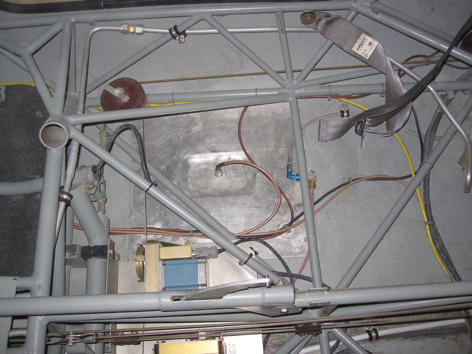
Grounds aren’t limited to wiring bundles. There are specific requirements for antenna grounding and distance separation, and we make compromises because of the limited space available on small airframes. Sometimes that has us rejiggering the wiring.
In this beginner’s tech guide focused on the stone-simple basics of electrically grounding typical avionics systems, we’ll look at some of the best installation practices and pitfalls, plus some of the more common symptoms that faulty grounding might create. In the research, we talked with professional avionics installers—and avionics manufacturers who build the gear, write the diagrams and work the tech support lines—for valuable installation tips in hopes you can get it right the first time.
Why Ground It?
Pardon the oversimplification, but we’ll cut to the chase. The concept of grounding avionics (the two-wire concept of a power lead [positive] and negative lead) isn’t much different than grounding any other electrical device. In the world of building aircraft avionics suites, maintaining good grounding is a means for less electrical noise from stray currents that can easily sneak into even the best audio control panels. Electrical noise (voltage differentials) and EMI (electromagnetic interference) can also shut down critical systems, including autopilots, EFIS and engine monitors.
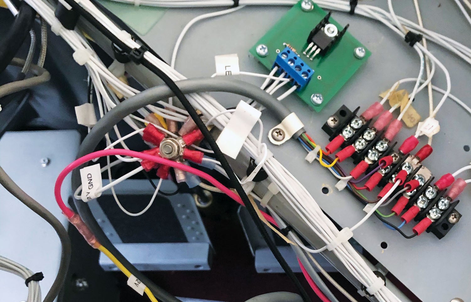
Of course, ground wires are also crucial for avoiding short circuits—or expensive avionics smoke shows. And completing the chain are fuses and circuit breakers—important protection in systems using two-wire connections. Circuit breakers and fuses open the circuit, stopping the flow of voltage when there’s a short. But good grounding is so important we build entire systems for the task, called ground buses. Or bus bars.
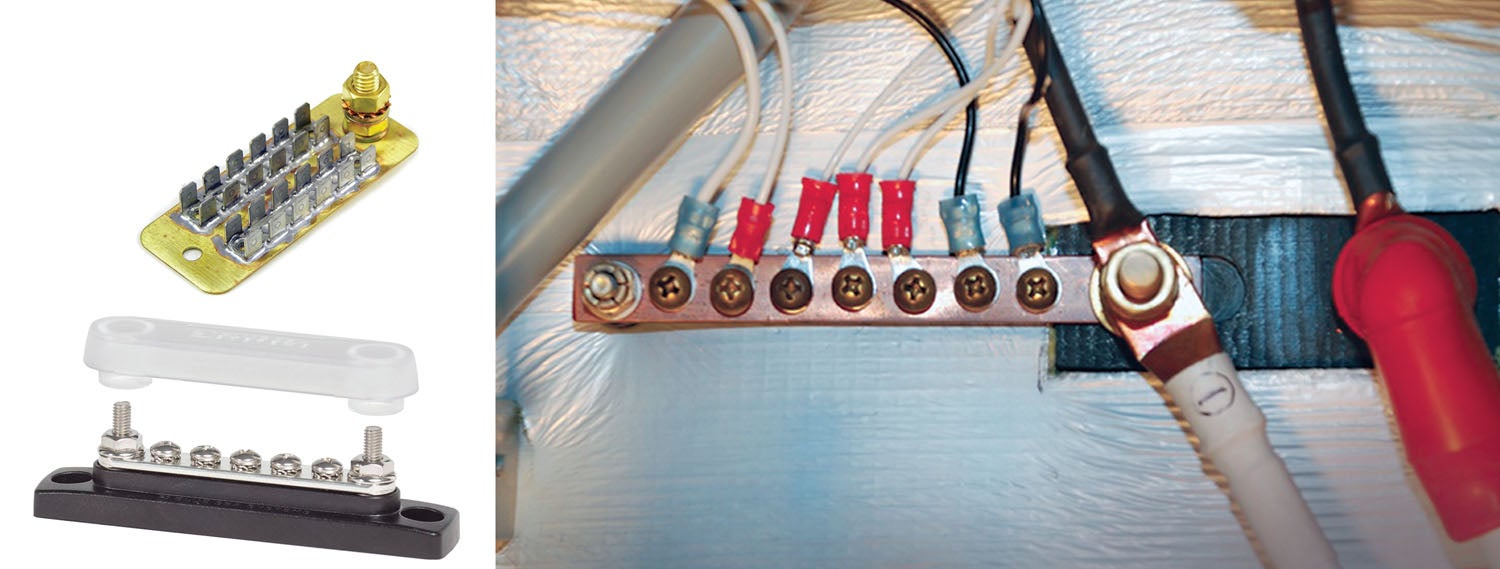
By building a ground bus, you essentially eliminate the airframe from the grounding task and the problems with loose connections, vibration, corrosion and insufficient contact between the ground wire (or ground lug) and the structure. In composite and fabric machines, they’re essential.
Common Ground
And when we talk about ground buses, don’t mistake them for switchable electrical buses (like an avionics bus and a main bus). There’s no switching the ground bus on or off. Don’t overthink it—a dedicated ground bus is simply a piece or pieces of copper for use as the main return point for all the negative leads in two-wire circuits. Dedicated ground buses have become the standard, rather than individual main grounds spread around the airframe.
When it comes to proper avionics system grounding, you’ll need a solid understanding of how an avionics manufacturer wants the ground wires constructed, routed and terminated. Thankfully, most installation manuals for the equipment we wire in our kits have been improved upon to avoid misunderstandings, miswiring and tail chasing. Still, you’ll need to brush up on some basic theory, terms and nomenclature that you’ll see in the wiring prints. There are shields, shield drains, electrical Highs and Lows—plenty of jargon. Moreover, avionics manuals are also written with the understanding that you have at least some knowledge of DC (and sometimes AC) electrical theory. Any doubts, work with an avionics shop to backstop your wiring (or have them build the more complicated and critical harnesses) and start thinking about the avionics early on in the build process. Here’s what we mean.
Smart Planning
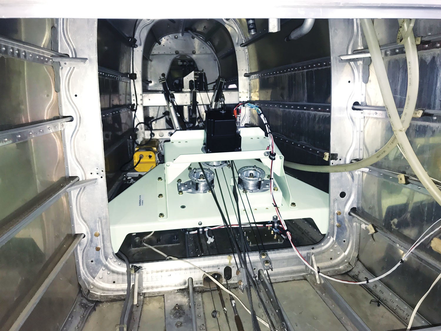
Manufacturers and techs we talked with stressed the importance of planning the grounding system (think of grounds as a whole and a major system in the suite) before you start wiring anything—and before you begin assembling and closing up the major structure. For the typical avionics configurations we work with, plan on bringing all of the major ground wires to a central location in the airframe that is convenient to access. With a dedicated ground bus, all of the grounds will terminate in the same area, and labeling the bus to match your aircraft’s wiring schematics is a must. This makes for easy troubleshooting down the road (you or someone else) while eliminating a tail chase when you’re trying to figure out which ground is causing grief. A centralized ground bus will also make it easier to ohm out the wiring during pin-to-pin troubleshooting.
A common location for building the ground bus is up at the firewall. Think of it as a hub, a meeting point for the system ground wires that run through the fuselage, in addition to the systems in the engine bay that need grounding. Worth mentioning is that you don’t want to use the engine mount for carrying electrical current (and no, not the fuel tanks, either—we’ve seen the horrors). The engine mount itself should be grounded, of course, and an appropriate ground strap should connect the engine to the firewall.
We’ve covered this before, and it’s always worth reviewing. It’s never too early to plan the antenna installation, and their proper grounding can make or break performance. Got an aluminum aircraft? Your job could be easy. Composite or fabric? Maybe not so much. More on antenna grounding in a minute. The planning stage is when you want to think about the antenna installation as a whole to get a feel for the amount of separation that’s required between antennas (it’s a wider distance than what’s practical), and in the case of grounding, what role the coaxial cable might play in critical systems should a bad ground generate noise. This can be a challenge given the small amount of real estate to work with, and WAAS GPS and communications antennas are critical. Map it out, and if there is any doubt on your choice of location, consult with the aircraft and avionics manufacturers, and talk with other builders who successfully built like-models with similar configurations.
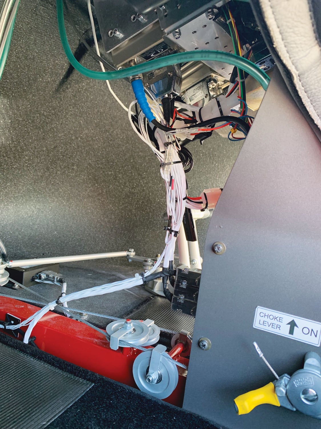
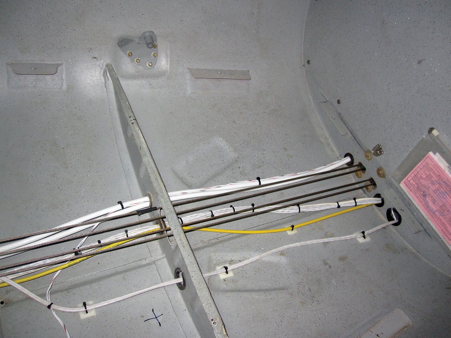
The planning stage is also a time to map out how you’ll route the harnesses, including audio system ground wires and coax. Avoid running audio harnesses next to devices with AC fields or even moderate pulse outputs. Strobes (including efficient LED lights), systems with large current draw, power lines, heaters, fans and servo motors are all known problematic systems when it comes to noise and interference. Solid grounding helps tame that dragon. When it comes to properly grounding audio systems (where faulty grounds might surface first), the pros have tips to bank on.
Avoiding Audio Noise
Modern audio panels from PS Engineering, Garmin and Trig have never sounded better, but the flip side to flawless audio quality is that you’ll hear the flaws that subpar wiring, and grounds in particular, can induce. Ridding audio noise is at the top of the list of struggles for amateur and pro installers alike.
Tip number one: Wire the grounds back to audio panels and not to the airframe. Grounding to the airframe instead of running a ground wire back to the device (an audio panel, for one) can cause ground loops from the avionics device to the point of the other grounded end. This is why things like headset and microphone jacks are isolated from the airframe (and instrument panel) and have grounds that run back to the audio panel, creating a single-point ground. And if a cabin speaker or sonalert is installed (they are becoming a rarity given the number of switched and unswitched aux inputs on audio panels), don’t ground the speaker to the airframe. Run a ground wire back to the source of the speaker audio—usually the audio panel itself.
Want a solid lesson in getting audio system wiring, right? Talk to audio panel pioneers PS Engineering. Founder Mark Scheuer has always been clear: A bad install makes an exceptionally good audio panel nearly useless, and many of the flaws are the result of installers not understanding how the system needs to be grounded. The good news is that audio installations have gotten easier, and the effort to wire a full-featured panel up has been curtailed thanks to pre-fab harnesses and wiring hubs (something PS Engineering offers). When wiring an audio system, do not deviate from the installation manual, and carefully read all the footnotes.
“The most important thing that’s required to build a quality wiring harness is to be able to properly read the wiring prints,” PS Engineering’s Scheuer told us. He’s right. There are critical instructions noted that, if not adhered to, can cause all kinds of troubleshooting (mainly unwanted noise). Where does the noise come from? Bad grounds, of course. We eyeballed both PS Engineering and Garmin install manuals for clues.
Garmin points out in its GMA 245/245R audio panel installation manual that because the audio panel is a point in the aircraft where signals from many pieces of equipment are brought together (it in itself is a hub), you have to minimize the effects from coupled interference and ground loops. We’ve all heard the unwanted noise signatures in the headsets. Ground loops are created when there is more than one path in which return currents can flow or when the signal returns share the same path as large currents from other equipment. These large currents create differences in ground potential between other systems operating in the aircraft, which can potentially produce an additive effect at an audio panel’s input—and there are lots of sneak paths in the most tightly designed digital audio panel circuitry.
One example (and a trap, of sorts) that comes to mind is the wiring for the audio panel’s entertainment input circuit, where the Low designated on the schematic isn’t the same as a ground. Moreover, the manuals point out specific ways to connect audio input jacks. Pay mind to shield drain symbology in the footnotes and in the schematics. An electrical drain in a shielded harness is a stranded wire that allows for a continuous, low-resistance connection to the cable’s metallic shielding throughout the entire run of the cable. Any electrical sneak paths “drain” to the main ground. You’ll see drains mentioned in various systems, so pay attention to the notations in the prints and don’t omit them. We’ve seen professional installers goof the drains, with disappointing performance.
Use caution when routing the harnesses under the panel and through the cabin. Coupled interference can sneak into the audio system harness when they are routed near large AC electrical fields, AC voltage sources and pulse equipment (strobe lights, spark plug leads, magnetos and even co-located displays). Interference can also sneak into the audio wiring by magnetic induction when they are routed near large AC current-carrying conductors or switched DC equipment. Here we’re talking heaters, solenoids, fan motors and even autopilot servos, which require critical grounding techniques.
When installing audio panels, if possible, keep transmitting systems like com radios and transponders away from the audio panel. Space is almost always limited, and this may not be possible, but devices that transmit any amount of power can cause fields to conduct into the audio panel, causing noise when transmitting as the currents fluctuate during the transmission.
On a side note, shielded wiring is imperative, especially at the audio jacks, including the aux input where you can plug in a patch cable to connect to your phone or music player. These jacks can be a major source of noise, especially ground loop noise, which has a signature hiss, hum and buzz that might vary with engine power settings. What you’re really hearing is the signal noise that results from differing voltages at the send and receive ends of the audio patch cable.
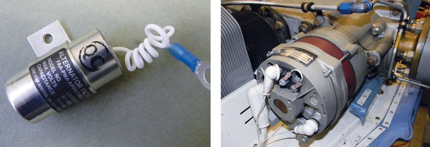
A ground loop isolation filter can help, but if the circuit is wired correctly, you shouldn’t need one. When running power and ground wires for devices, keep those pairs away from wired audio connections. Maintain good practices throughout the entire audio system and use isolating washers for audio jacks to prevent ground loops. Audio jacks that make contact with the metal instrument panel (without the use of isolating washers) create an unwanted second ground path.
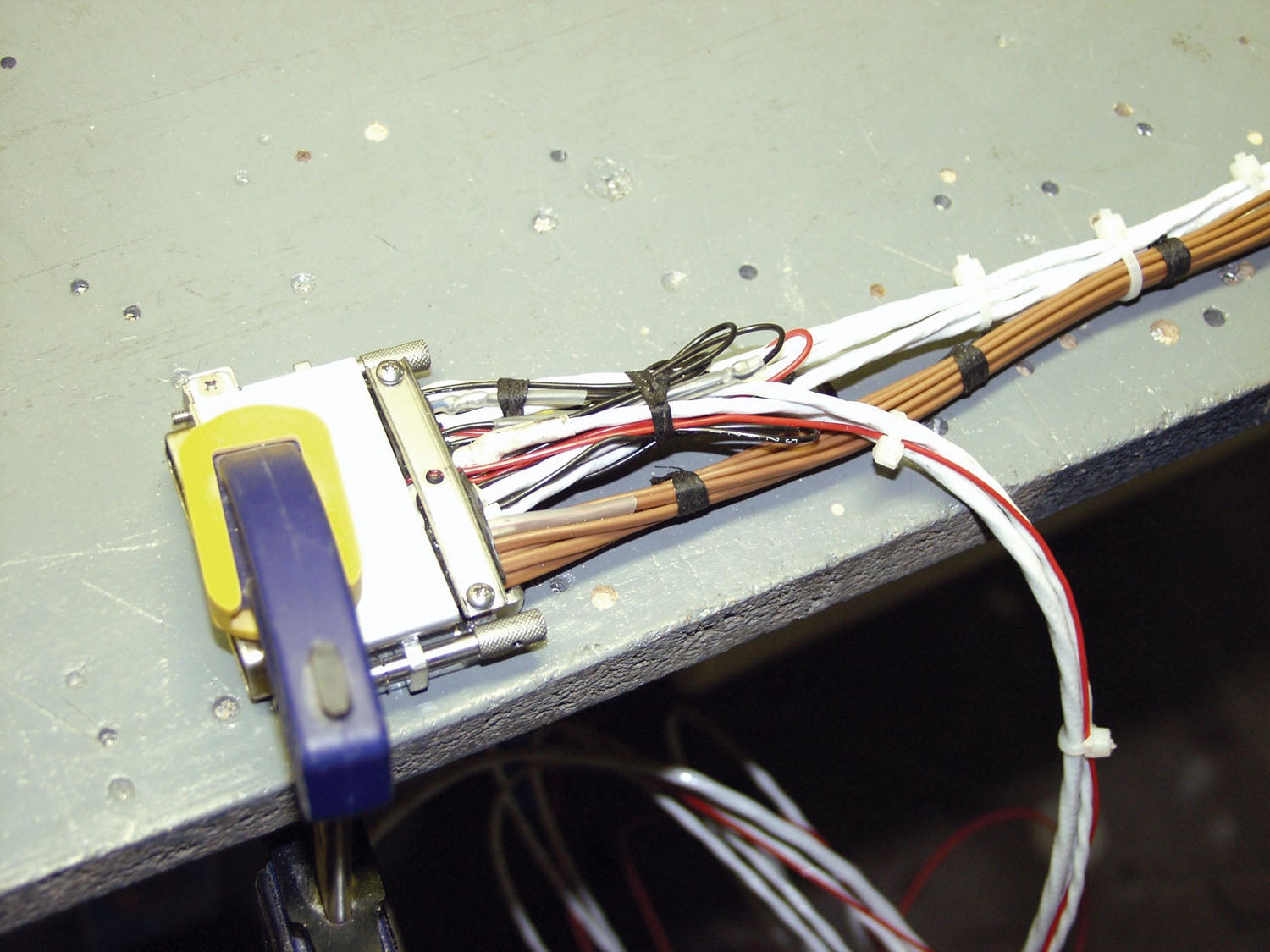
For avionics that use the metal slide lock or jackscrew backshells, ground the shields of wiring that are shielded at the unit end directly to the backshells using ring terminals. This will offer a good return path for the wire shield for the wiring that requires the shield termination. We’ve lost track of the number of audio installations we’ve troubleshot where the audio panel grounds were out of place—or missing. Last, wire the grounds back to audio panels and not to the airframe.
Don’t underestimate the importance of using quality accessories. Use switches, fuses and circuit breakers (new ones) rated for the voltage/current that will go through them, using the installation manual as reference. Faulty switches and underrated fuses and breakers can cause trouble.
EFIS/Engine Monitoring Grounding Issues
If you’ve battled electronic flight instrument problems—magnetic heading issues in particular—you might have learned the hard way that proper grounding is a must. Again, the defense starts in the planning stages. Once you decide where the remote heading sensor (magnetometer) will be installed, survey other systems that will be collocated.
For example, there’s a tendency to ground heated pitot tubes, wingtip strobes and other lighting inside the wing, but the pros will tell you that’s a bad idea. Instead, run the lighting system’s grounds to the ground bus. For the wing-mounted magnetometer, a dedicated power ground should be used and returned as a twisted pair, along with the power source back to the ground bus.
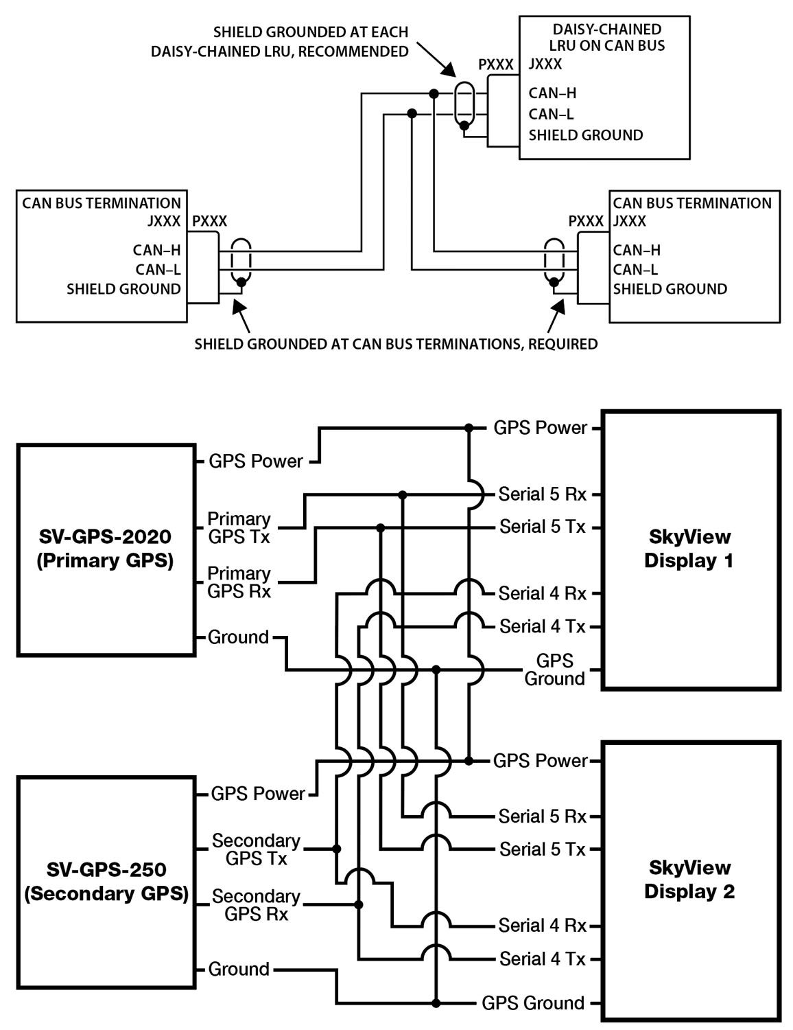
Garmin advises to use caution with wing root Cannon plugs used for Can bus connections to and from the magnetometer because the multi-purpose connector can also carry power and ground wires for, say, a high-current circuit for a heated pitot tube. While the magnetometer’s shield wire can run through the Cannon connector on a dedicated pin, there will still be a short run of the data bus that’s unshielded and prone to interference problems. Isolating the Can bus data wires is the best bet, even if it means running dedicated wires for the device back out of the wing to the ground bus while maintaining physical separation with the device’s twisted pair databus harness with high-current carrying wires. Easier said than done in small aircraft.
Pay particular attention to the grounding instructions for autopilots—and autopilot servos in particular. As one example, in Garmin’s GFC 500, the trim output commands come directly from the autopilot pitch servo to the trim motor (for automatically running the pitch trim when the autopilot is engaged). The output from the pitch servo to the trim motor is grounded to the shield on the servo side of the circuit and grounded to a common airframe ground. Any deviations to this wiring can cause sizable interference whenever the trim motor is running—and it’s enough to disengage the autopilot and cause noise in the audio system if the com antenna coax is in close proximity, which it often is.
Grounding problems will create all kinds of issues with the magnetometer’s heading resolution and even with other functions within the EFIS architecture. You could see intermittent heading error, you might struggle to get the system nulled during the configuration stage, and in some cases, the EFIS may not work at all, showing invalid heading, attitude and other flight data. Engine monitoring systems are also at risk.
Dynon’s engineering points out it is vitally important that all major components within its systems—including engine sensors, the SkyView display, the engine monitoring module and the electrical system—share the same ground and to ensure that there is virtually no measurable floating voltage between these grounds.
Dynon says that running a ground wire from the EMS (engine monitor) to the engine block may not entirely solve the grounding issue, as this adds just a small wire in parallel with another much larger wire, and the load will get transferred to this smaller wire (which itself is resistive due to its small size). You likely won’t see any improvements. Run the grounds to the bus.
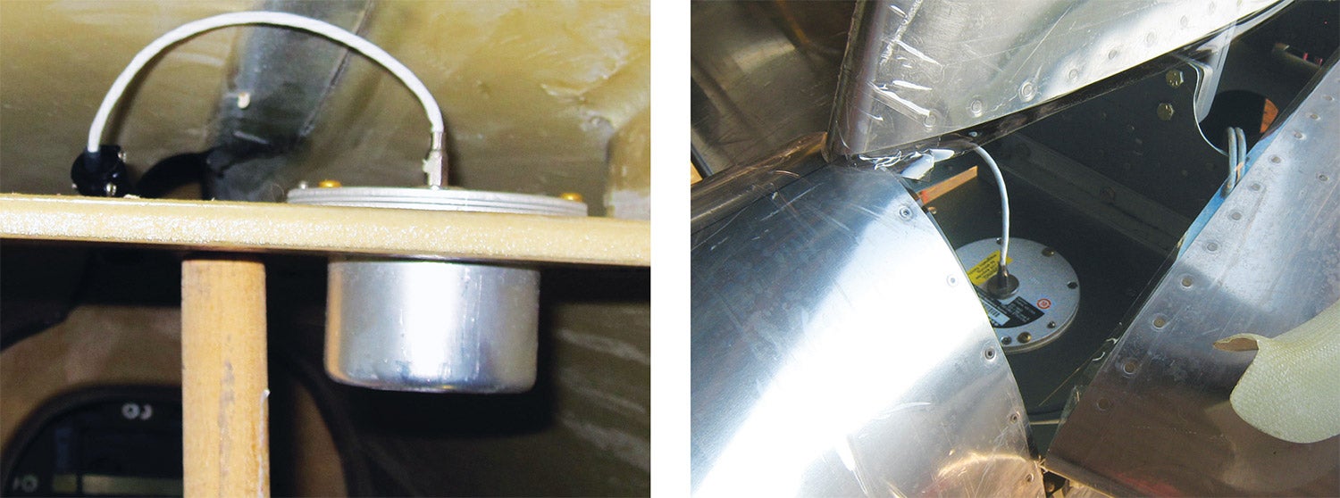
Antenna Ground Planes
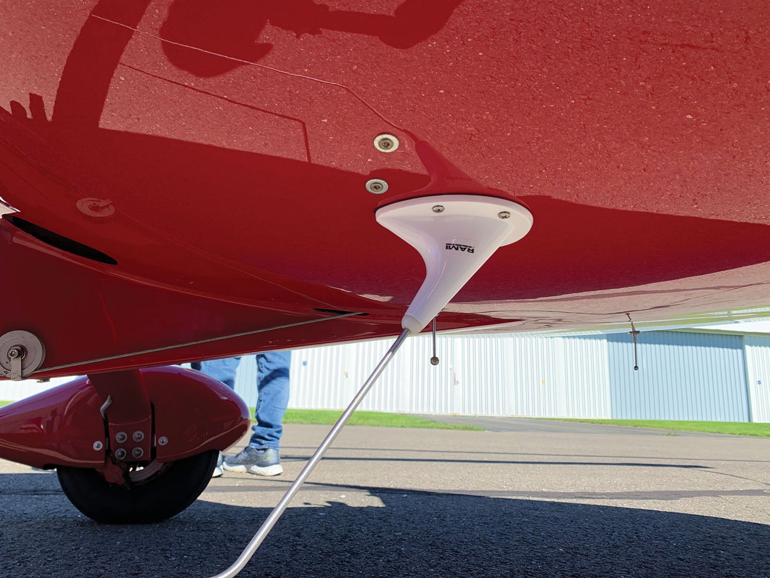
Don’t underestimate the importance of proper antenna grounding, and dealing with antenna farms is a challenge on small airframes. We asked the engineers at antenna manufacturer Comant Industries if there’s a general spec for designing the size of a ground plane, and it reiterated what we already know from years of antenna installation experience: Bigger is better, but that’s not always possible, especially on fabric and composite installations. At a minimum, a circular ground plane’s diameter can’t be any shorter than the antenna’s base.
Poor continuity generally means poor performance. Perhaps you’re fabricating a mesh ground plane for an antenna on a composite structure. You’ll need to be certain there is proper contact between the antenna’s mounting screws (oftentimes where the grounding takes place) and the mesh. While this is a very basic concept, it’s one of the easiest tasks to get wrong. The FAA’s Advisory Circular AC 43.13-2B is a good place to learn about acceptable methods. A ground plane may not be required for all antennas, but it’s still recommended. That’s what Garmin says in the installation manual for the WAAS antenna used with its G3X Touch integrated avionics system, and they suggest the conductive ground plane be a minimum diameter of 8 inches. Like many antennas, the WAAS antenna is grounded through the mounting hardware and the coaxial antenna connection.
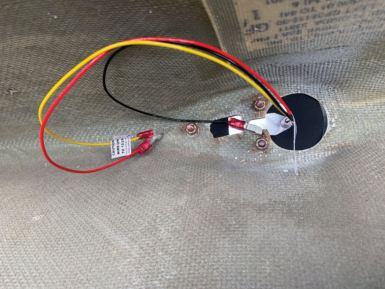
For fabric aircraft, the drill is to fabricate a ground plane using heavy foil tape or other metallic surfaces for a solid bonding of the antenna. Since there might be limited structural space available for mounting antennas on fabric aircraft, the installation of some systems just might not be possible. Again, AC43.13 provides guidance.
The Garmin manual suggests that the mounting hardware (washers and nuts) and doubler plate should make contact with an unpainted grounded surface to ensure proper antenna grounding, so prep the surface accordingly. It is important to have good conductivity between the coaxial shield and the ground plane. The bottom of the antenna base doesn’t need to make contact with the ground plane because the antenna will capacitively couple to the ground plane beneath the paint or covering.
When in Doubt
Our thanks to the folks at Garmin’s Team X Experimental avionics engineering group for their advice and input here. It was obvious in talking with them that they have helped plenty of builders fix issues that were the result of faulty grounds, mostly because the installers didn’t read the schematics properly. That aside, there is a grand takeaway.
“Ask any one of our engineers, and they’ll tell you they want to see a two-wire circuit on all of the individual LRUs in a Garmin integrated suite,” Garmin’s Justin Cobb told us. Whether it’s a basic stack of radios and a single EFIS, or a multiscreen G3X Touch, he’s talking about running dedicated ground wires back to a common airframe ground rather than a localized ground connection that can cause havoc from (and to) other collocated systems.
Given the importance of getting the wiring right for today’s integrated digital avionics, there are plenty of resources to help you along. Browsing the forums for various kit models, we found that grounding issues are front and center, and there is much to be learned from others who either solved nagging issues or got it right the first time. The EAA and AEA (Aircraft Electronics Association) are also good sources of technical knowledge. Consider taking one or more of its avionics installation courses, where you’ll get a good primer in grounding and best wiring practices.
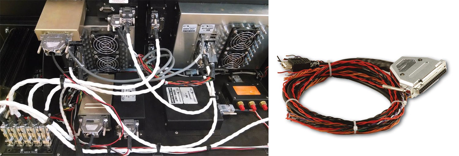
Last, consider using wiring hubs. While you still need to deal with grounding, prefabricated harnesses sourced from reputable and skilled suppliers can be a good assurance that the power and ground wires within the harnesses are done properly. We’ll pick this discussion of grounding back up in a separate follow-on article on wiring hubs and electronic circuit breakers in a future installment of Avionics Boot Camp.
Photos: Larry Anglisano, Marc Cook.
![[Credit: JetStream Rider]](https://www.kitplanes.com/wp-content/uploads/2026/04/AdobeStock_345999332.jpg?w=218&h=150&crop=1 "2026 Avionics and Lights Buyer’s Guide")
![[Credit: Dynon]](https://www.kitplanes.com/wp-content/uploads/2026/04/EMS-stand-alone_HDX.png?w=218&h=150&crop=1 "Dynon Unveils Scalable Engine Monitoring for Kitbuilders")


I have realised how critical this is over the years with very unusual problems directly linked to a bad earth .
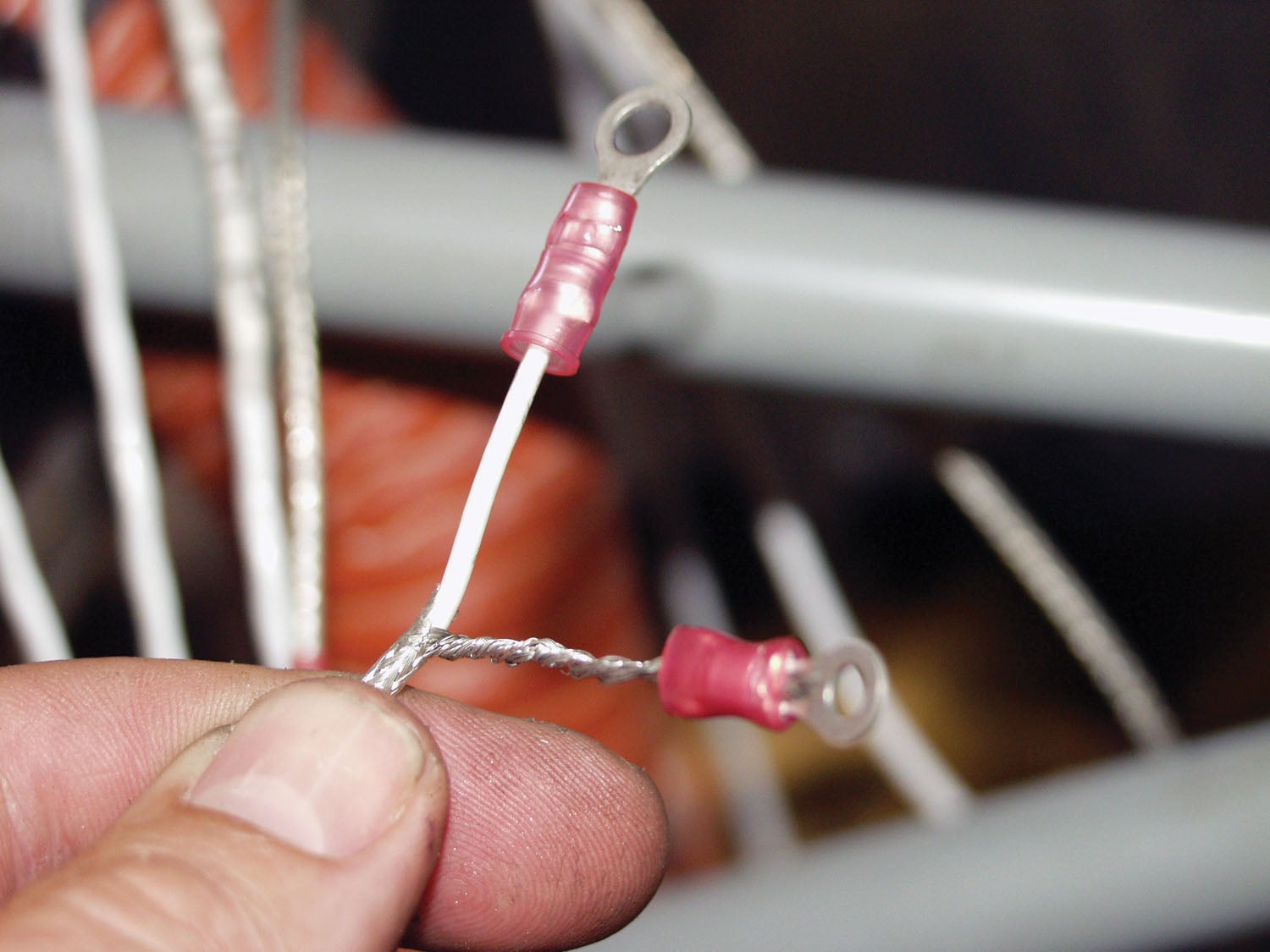
Some cables are crimped to the lug , while others are soldered . I personally prefer soldering cables to lugs due to living at the coast and finding corrosion at the lug between it and the cable over time , often not very long at all .
Your thoughts .
Its unfortunate how so many in aviation refer generically to “grounds” or “earth”, leading to problems generically blamed on a “bad ground”. We would be much better off if those in the know would promote more appropriate terms such as “power return”, “signal return”, “common reference point”, “ground planes”, “shields”, etc. Then an appropriate discussion can be had on how, when, and where to control the flow of power currents, signal currents, and potential conducted (electrical) and induced (E or H field) interference. When appropriately identified, terms such as “common or single point” have some relevance. In a building, the “earth” means something, not so much in a vehicle (unless on terra firma and concerned about antenna performance or static electricity.).
I did a Dynon heated pitot tube installation last year. I was surprised to see that they wanted to run a ground wire back from the unit, and not just ground to the airframe. The instructions said that running the ground through the airframe will induce noise. First time I’d heard of this, but now I’m being more careful, especially with the high current draw loads.
The heated pitot issue is a classic result of the poor discipline in nomenclature and convention. The heated pitot does not have a ground – it has a power input conductor and a power return conductor. The metal assembly itself is another issue, and is generally directly connected to the airframe by its mounting hardware, much like an antenna. If the pitot heat power is carried by a twisted pair, much potential noise generation is avoided. If the power return is “grounded” at the probe location of the airframe, then you have a loop antenna, where anything in the vicinity of the probe power conductor anywhere along its length will may receive h field noise associated with the noisy power controller for the heater. When the power is provided by a twisted pair, the loop antenna is small (between the two conductors) and is pretty much cancelled. Using the airframe as a “ground” or power return, is a holdover from old vehicles with simple and insensitive electronics (older cars, etc). The proper method is twisted pairs for all power supplies, and twisted pairs or triplets for all non-RF inputs, shielded inputs for all RF or very sensitive inputs. The only downside to such pairs is weight, so where the power is not noisy (like a linear circuit, not a switching circuit), and the power can be routed close to the well-bonded airframe separate from sensitive stuff, can the power return be connected to the airframe near the load. All the power returns go the the “single point” common, directly connected to the battery return (-). All the signal returns go to either the same “single point” or to the signal’s minus input on the instrument if the signal is true differential. Pay attention to this and the magnetometer will have no interference from your systems, the radio audio will be quiet, you won’t hear an alternator whine, etc. Ignore it and you can see those issues and more, like an aircraft problem I saw and fixed where adjusting the cockpit lighting affected the fuel quantity displayed.
I agree with 99.9% of Erik’s comment. I would only add that it is not entirely necessary to use twisted pairs of power input and power return wires. Current flowing through each wire generates a magnetic field around the wire. Do a web search for “magnetic field around a long straight wire” for a detailed explanation. The power input and power return wires generate opposing magnetic fields due to the current flow in opposite directions in the two wires. These opposing magnetic fields cancel each other pretty well. The advantage of the twisted pair is that twisting the wires together results in them staying in close physical proximity to one another, ensuring the magnetic field cancellation. But you can achieve results almost as good by running the power input and power return wires parallel to each other and keeping them in close proximity to each other with heat-shrink tubing, cable ties, lacing cord, and/or braided sleeving, aka “snakeskin”. One disadvantage of twisting the wires together vs. running straight wires in parallel and keeping them close together is that the twisted pair requires more wire to get from one place to another. (Another disadvantage is the twisted pair requires a little more space to get through snap bushings etc.) The length increase results in a small increase in overall wire resistance (and hence voltage drop) and weight, and if you’re using a harness made by a vendor, you may not have enough wire to get from one place to another. I tested the straight wires in parallel approach with pitot heat wiring running close to an ADAHRS with a built-in magnetometer, and the PFD compass dial didn’t move as I applied and removed 10A of pitot heat current. If you use the airframe for the power return, you will be very hard pressed to achieve magnetic field cancellation. That’s because the power return current flows diffusely through the airframe, instead of being concentrated in the power return wire. And don’t forget that aluminum oxide is an insulator, and anodization of airframe parts also creates a surface insulating layer on the parts. Consequently, running a separate power return wire may save you from a difficult-to-troubleshoot grounding problem somewhere down the airway.
A small point of nomenclature… The author wrote that “Circuit breakers and fuses open the circuit, stopping the flow of voltage when there’s a short.” An open breaker stops the flow of current. Voltage does not flow (voltage it is the difference in electrical potential that result in the flow of current). As an analogy, we don’t shut the fuel valve to stop the flow of pressure. We shut the fuel valve to stop the flow of fuel.
Greet Article. My Colleagues and I know that how to ground was an issue but were not clear on how to approach the problem. Thanks for clearing this up.
Comments are closed.