 As anyone who has built a metal airplane knows, it’s hard to escape some fiberglass work. Unless you are truly a master metalsmith, you will work on composite wingtips and cowlings. Before the composite guys get smug, I will point out that they are probably going to be doing (at least) some metal engine baffles—so it mostly evens out.
Just like every other metal-aircraft builder, I have had to develop fiberglass skills—doing layups, filling pinholes and smoothing out contours with resin and micro (or other fillers). It’s a love/hate relationship. I actually love the fact that you can do pretty much anything with fiberglass—and if you aren’t happy with the results, you can “erase” it with a sanding tool and start again. But I simply hate the mess and the repetitive nature of sanding, filling, sanding, filling…ad infinitum.
I have had to make composite tips (tail and wing) fit by cutting and re-bonding. I have had to fix warped parts with filler and lots of sanding. And I have performed major surgery on cowls and fairings to get the air to move past discontinuities properly. It’s just part of the road to finishing—a road with few shortcuts. Unless you know a good glass airplane builder who will trade you their skills for a nice set of engine baffles.
Today’s Challenge
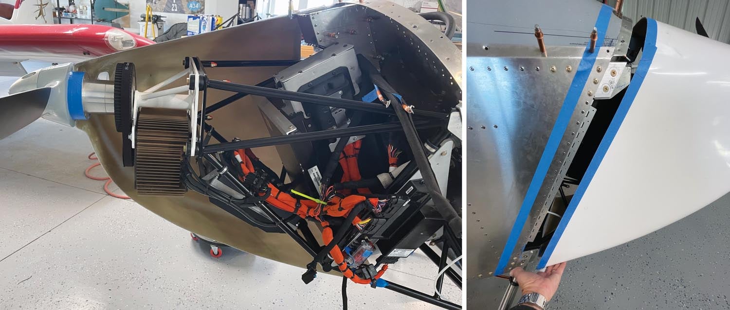
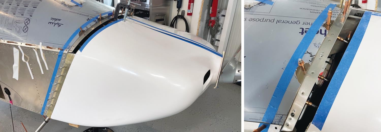
So what prompted this particular set of musings on the “joys” of composite work? Well, it turned out that the cowling for our eXenos project needed to be lengthened as part of the process of mounting a completely different powerplant than what the original design called for.
Why? It’s the pain of being an early adopter. As one, I received an engine mount for the electric propulsion system that was longer than intended. Bad news for me but the good news is that all of the production versions will be the correct length to allow use of the standard, unmodified Xenos cowling. Progress!
When all was said and done, with the early, too-long motor/battery mount and installing the electrics, the stock cowling was about 2.5 inches short of reaching the firewall when the front was butted up against the back of the propeller. Rather than wait for the new mount, we modified the cowling.
While we could have attached the cowling to the firewall and done considerable re-contouring up front, the thought of forming shapes in foam and reworking contour lines lost out to the simple task of bonding in flat strips on the sides and bottom to match the slab nature of the fuselage. We had to do some work to make the curved top fit properly, but at least we could do that without making molds.
So let’s take a walk through the process we used to lengthen the cowling for this project. You will be tempted to say, “Hang on, this simply isn’t relevant to me. I am going completely stock and my factory cowl will fit perfectly!” Let me point out that a lot of metal airplane builders over-trim their stock cowl and end up making it too short—so they need to add some back in. Why does this happen? Composite cowlings are a little like octopus skins—they keep changing shape until they are in their absolute final position. So trimming a little that seems just right when the cowl is not in its final position often means you end up a quarter-inch too short. It doesn’t fit until it, uh, doesn’t fit! Love/hate, remember?
Establishing “Truth”
In many airplanes, both the fuselage and the cowling are tapering toward the nose, so getting a good fit is not always easy. Tapers and compound curves are hard to fit. Add to that the fact that most cowls are split—either top to bottom or side to side (ours is side to side). As a result, you quickly find that the cowling doesn’t want to hold any particular shape until it is actually mounted—but you can’t mount it until you freeze the shape. Catch 22. (If you caught Larry Larson’s multipart series in our March, April and May 2023 issues on fitting the RV cowling, you know part of the story already.)
The way to deal with this is to figure out how to establish a baseline, a “truth,” if you will. Once you pin the cowling in a specific position, you can then adjust from there to get a good fit. With a cowling that is too short, the problem is compounded because it is literally floating in space until you lengthen it somewhere.
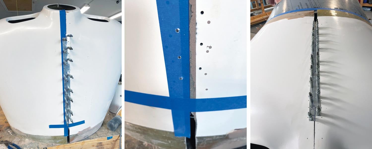
For our project, the slab side of the fuselage provided a good place to establish truth, so the first point of attack was to add some material to the back edge of the sides. Once we added material to the sides, we could trim and fit those to where it could be Clecoed in place. Then we could deal with the curved top or the flat bottom—whichever seemed more appropriate when we got to that point. But once the sides we pinned, we had truth and everything else could be adjusted to fit.
Lengthening With Scarf Joints
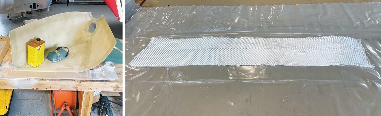
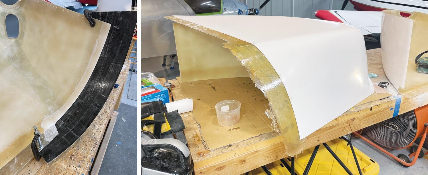
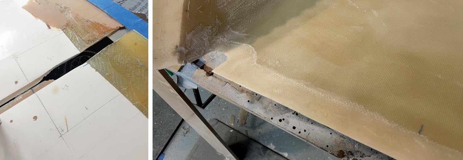
How do you add material? Well when it is flat, it’s pretty easy—you start with a scarf joint. What this means is that you want to taper the surface to which you want to attach the new material. An aggressive sanding disk on an angle grinder or hand sander will generally do the trick. We laid the cowl on the workbench, outside down, then ran the sander along the edge, tapering it to a fine knife edge. With a layer of gelcoat on the outside, this was easy—you could tell that you were down to the knife edge when you saw the white appear. We then tapered the joint in about an inch, uncovering the layers of the original cowl like sedimentary rock on the edge of a reservoir. This taper is the key to a good scarf joint—the added material will be tapered in the opposite direction and the overall thickness will remain the same all the way from the old part to the new part, with the outside edges lining up due to the knife-edge taper.
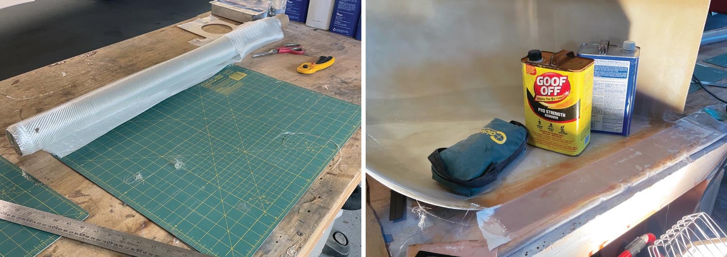
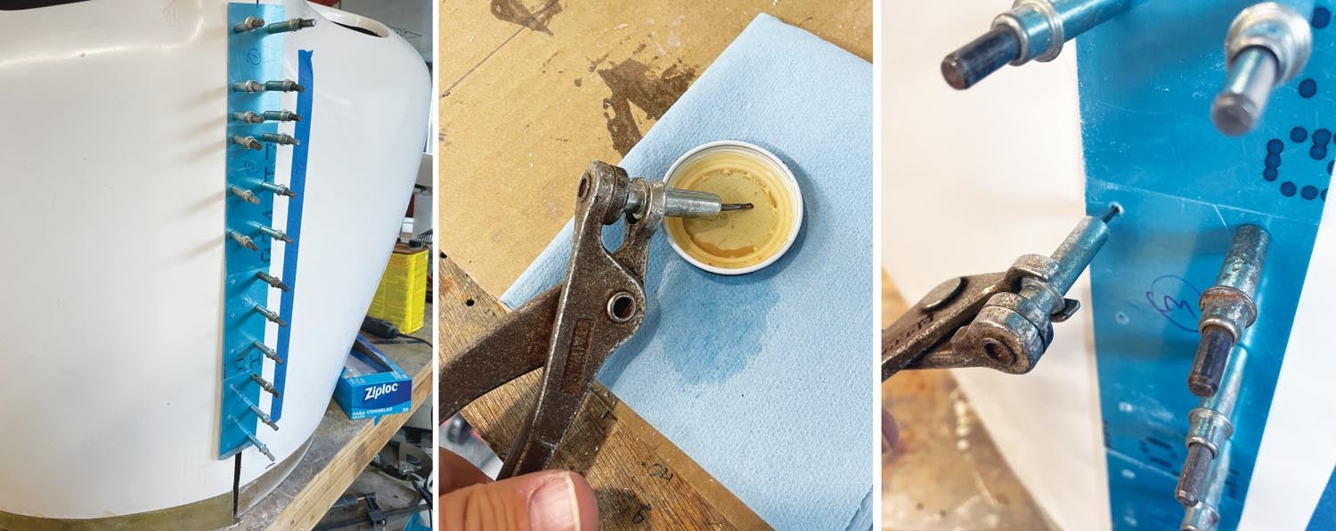
With the joint prepared, I now needed a mold—this was nothing but a backing surface that was straight and flat, covered in something to which the fiberglass resin wouldn’t bond. Plastic sheeting or clear packing tape is good for this. I found a nice flat piece of particle board in my scrap bin, laid it on the workbench, then laid the cowl “side down” on that, leaving sufficient board sticking out to add the 3 inches of glass that I needed. I then drilled a couple of #40 holes in the cowl and through into the board and used silver Clecoes to hold the cowl to the board.
Yes, I’m drilling extra holes in the cowling I won’t need later. Not a big deal. You are going to be doing a lot of finishing and filling on the cowl anyway so filling a couple of tiny holes is in the noise. Make your job easier—fasten things down now and fill the holes later. It’s really better this way.
With the cowl and mold prepared, it was time to cut some fabric and make a mess! I used a roll of BID (bidirectional) cloth and cut progressively narrower layers—because I wanted an overlap of 3 inches, I started with two layers 3 inches wide, then one layer 3.5 inches wide, another 4 inches wide, one more 4.5 inches wide and then, finally, one 5 inches wide. This gave me a taper to match the scarf on the existing cowl. This bundle of layups went on plastic sheeting to be saturated by activated resin, another layer of plastic, complete wetting out of the matrix and finally, application to the cowl and the mold sheet. A layer of Dacron peel-ply finished it off, with a final squeegeeing of excess resin.
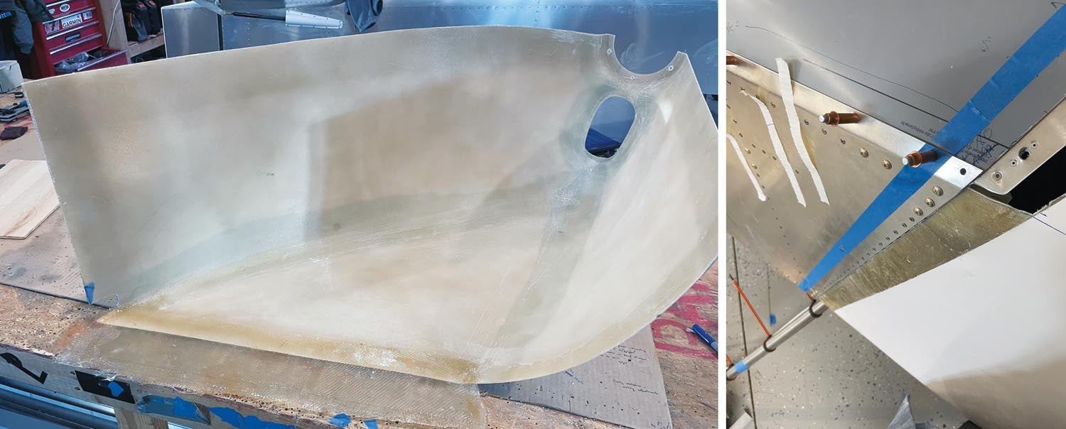
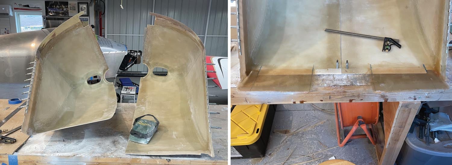
Curing time complete, it was a simple matter of separating the peel ply from one side, then popping the cowl with its new 3-inch extension off of the mold. I now had 3 more inches to work with on the sides (I repeated the process for the other half of the cowl of course).
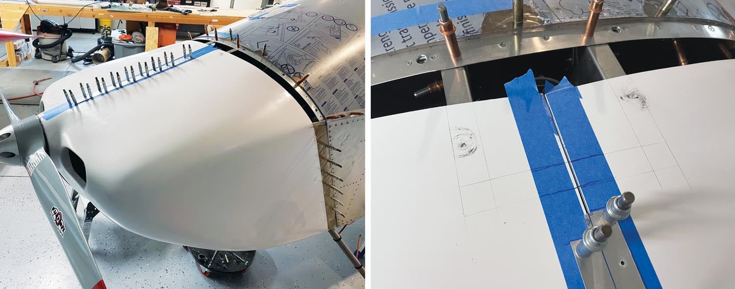
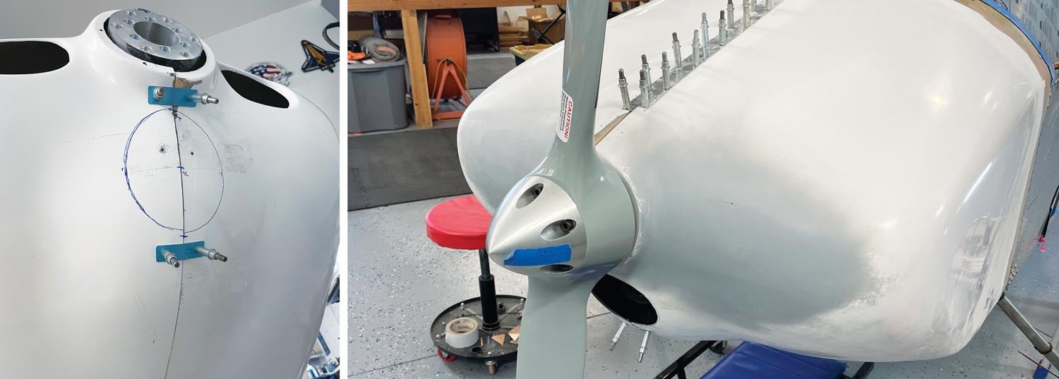
Now came the usual fit/trim cycle—using the back of the prop as “truth,” I trimmed the new back edge (on each side) until it was close enough to Cleco to the cowling’s attach points (in this case, hinges). Two holes drilled for silver Clecoes held each side rigidly in position so that I could continue trimming and fitting, eventually drilling all of the holes to the attaching hinges. I now had the cowl positioned so that I could work on the top. The bottom was going to be a simple job and its final position might depend on how the top turned out, so I left it for last.
Getting in Deeper
Creating the curved extension on the top was similar to the process for the sides, except that the “mold” needed to be curved to follow the contours of the existing cowl. A curved backing isn’t all that hard to create, however, so long as you’re dealing with a single curvature—or something close to it. I suspect that there is a bit of compound curving going on with the Sonex cowl, but it was small enough that we could get away with using a piece of heavy poster board for the curved mold, taping it securely to the outside of the top portion of the cowl, then laying the material into it. Care had to be taken in trimming because this truly is a case of “it doesn’t fit until it fits,” so you have to sneak up on the final trim.
Once the sides and top were more or less in place, we fit the center seam—which, in all the perversity of working with fiberglass, now had a gap that had to be filled. We did this to a final fit by building a “bridge” of scrap aluminum, Clecoed in place on the outside after covering it with packing tape. Working inside the joined cowl, I laid in the necessary glass to re-joint the two halves. When it was all set, the entire cowl gets Clecoed back in place to check the fit, then split the cowl down the middle, leaving the specified 1/16-inch gap. You’ll see in the pictures that we made a strip of aluminum match-drilled to our hinge and used that on the outside instead of trying to use the hinge on the inside during all this fitting. The same thing was done on the bottom.
Finally, the bottom needed to be extended and, again, this was as simple as the sides. With some rough trimming and aluminum splices holding the bottom center seam together, we simply added 4 inches to the back of the bottom, then trimmed to fit. Since an exit is required for cooling air, we simply didn’t do the extension in the middle area as shown on the plans and finished the back with hinge material as per the standard Sonex design. We now had a cowl that fit all the way around and matched the fuselage nicely.
One Step at a Time
When first faced with a project like lengthening a cowl, it seems like a daunting challenge and trying to figure out how it is all going to fit is a puzzle. But just like all aircraft building, you have to stop trying to look at the whole picture at once—you need to break the project down into single steps. Determine how much you have to add all around and add some margin for error—maybe 20%–25%. Figure out the easiest place to add material so that you can “pin” the project in position to figure out the next step. Scarf your joining surface. Prepare your layout. Saturate with resin. Lay it in place. Let it cure. Then mount and trim to fit. Now begin the next area.
It isn’t all that hard, just messy. But so is drilling lots of repetitive holes or spraying metal primer—or if you’re doing tube and fabric, sanding all that area again and again! If you’re a wood builder, tell me about all those rib pieces and gussets! Airplane building is messy, no matter the material. In the case of fiberglass, wear old clothes, cover anything in the shop that doesn’t react well to dust and find yourself a good set of safety glasses and a dust mask. Then have at it!
And as I said at the start—if you don’t like the results, sand or cut them away and start again. That’s the beauty of non-structural fiberglass work—it’s all art and it can all be fixed.


Great article, thanks. What weight BID cloth did you use?
I believe that this was 9 ounce BID from Aircraft Spruce – that’s what I usually have on hand, and I did this with whatever I had on hand….
Interesting and unusual fiberglass project. I had “help” when fitting my fiberglass cowl and didn’t understand a lot of what was happening. Thanks for taking the time to explain some pieces of the puzzle. Really appreciate it.
Comments are closed.