Funny the irony of the title… we’ve just been through the coldest, snowiest week in the last 50 years in Northern California, and here I am writing about summer. (It isn’t every day it snows in downtown San Francisco.) Wrong summer, though. The summer we will examine this month is known as either a summer or an adder. It simply adds together various signals and gives the arithmetic sum of those signals.
Why? When I get half a dozen inquiries about how to do something in a short span of time (like last month), I get the idea that perhaps it is something that more than a handful of people would like to build. In this case, all of the questions were similar: Ive got half a dozen audio signals Id like to monitor at the same time, but I don’t have the room for an audio switching panel. Audio signals? Alarms from the engine monitor, remote nav receivers, Walkman, FM radio and lots more. The requests were all the same: I have a single aux audio input on my new com radio and half a dozen things Id like to put into that input. How do I do that?
Its simple, and its complex. The problem is that you cant just twist together half a dozen (or two, for that matter) outputs and tie them into one input. I wish it was that simple, but its not. The fellow who engineered the audio output expected to see a single resistive impedance to feed that audio into. Generally in the aviation world when we engineer a low-level (headphone level) output, we expect to see somewhere between 150 and 1000 ohms, nominally a standard line impedance of 600 ohms. A little above and a little below isn’t too bad, but tying two of them together into a 600-ohm input means that not only is your output looking at that 600 ohm input, but it is looking at the other output as well, and in general that will be measured in tens of ohms. Not a good thing.
Electronics to the Rescue
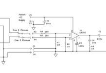
My old friend the op-amp makes a nice summing amplifier. Take a look at the schematic. U1A, an LM358 op-amp, has two inputs. The (+) noninverting input has a very high input impedance. The (-) inverting input has a very low input impedance and makes a dandy summing junction. The voltage gain of the amplifier is simply given by the ratio of the input resistor to the feedback resistor. For example, the voltage gain of Input 1 from the Input 1 terminal to the Out to Radio terminal is given by the ratio of R12 to R2 (in this case 22k/22k) or a gain of 1. That is, if you put in 1 volt of audio, you will get out 1 volt of audio.
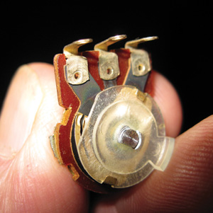
A variable resistor (potentiometer). Note the two little spring brass wipers contacting the underlying carbon horseshoe resistor element. The two outer terminals contact the resistor element, and the center terminal contacts the brass wipers.
But, you say, what good is that? Well, the gain of Input 2 is exactly the same thing, but the audio of Input 2 is added to the audio of Input 1 and both of them appear at the Out point, and that is the intent of this little box. Not only that, but because the impedance of the (-) inverting input of U1A is near zero, there will be a tiny (too small to measure) voltage at either end of C1, and thus Input 1 and Input 2 are isolated from one another, but added together to go to the aux audio input on your com radio. The same goes for Input 3 and Input 4. They are all isolated from one another but appear added together (all of them) at the output of U1A, and that is what we intended.
So what are R1 through R8 for? Well, not all of your inputs are going to be at the same level. You will probably want to have some louder (like alarms) than others. Those four potentiometers (variable resistors) will let you set each input to the loudness that you like, each independent of the other.
Duly Noted
But the music, Jim, the music! Sigh. OK, well push the summing principle a little harder. And here I cant really predict what your music source is going to want to see for a load. Some music boxes don’t put out a real airplane headphone level, so we will need some gain here. How much? Dunno, but Ill tell you how to modify the circuit to get any gain you want (within reason).
U1B, same song, second verse. Input L and Input R (left and right) are summed at the (-) inverting input of U1B. Once again, I made a gain of 1, but you can have any gain you want. And, once again, the inputs are totally isolated from one another.
But what about RL? Like I said, I cant tell what output impedance your music box is going to want to see, so these load resistors will provide a proper load to your music box. This is the only thing you will need to determine for yourself, and then choose the load resistors appropriately. Me? With current design music boxes Id start out deleting (open circuit) both RLs and put them in only if the music is distorted or unclear. The output of U1B is summed into the same (-) input on U1A as Inputs 1, 2, 3 and 4.
Let me make a lateral arabesque here. For 20-some years now Ive been tossing around the terms resistor and potentiometer without telling you anything about what they do or how they are made, so let’s take a little side trip. A resistor is nothing more than a device for limiting current. How do we do that? Quite simply. Use a lousy conductor from one point to another. What is a lousy conductor? Carbon comes quickly to mind.
As a matter of fact, back in WW-II we made resistors out of pencil lead, plain old carbon graphite. While these worked electrically, they left a bit to be desired mechanically. They cracked, they broke, they got hot and melted. Over the years weve struggled with how to make them electrically sound, mechanically rugged and cheap.
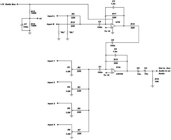
The schematic.
The Details
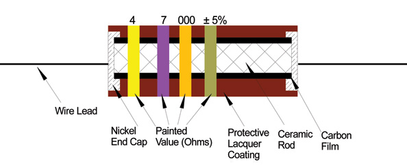
Take a look at the drawing. We start out with a teensy-tiny (50 thousandths in diameter) solid ceramic rod. We vaporize carbon in a vacuum and let it deposit out on the rod as a film (about one ten-thousandth of an inch thick). We then epoxy nickel (or brass) end caps onto each end of the ceramic-carbon rod, spot weld a wire onto each cap, give it a protective coating of paint (usually lacquer), and then color-code the value and tolerance onto the body of the resistor with paint stripes. After all this rigmarole, I buy them for half a cent apiece.
The potentiometer? Its nothing more than that fixed resistor we described above, bent into a horseshoe shape plus a spring brass moveable contact (wiper) that will slide along the carbon element and pick off whatever fraction of the voltage across the element you want. The large ones are sometimes called volume controls, and the small ones are sometimes called trimpots (trimmer potentiometers).
Oh, yes, the circuit mods I referred to earlier. If you need gain out of the main U1A amplifier, simply increase the value of R12. However, if you do this, you must decrease the value of C6, the noise filter. For example, if you want a gain of 10 out of U1A, you increase the value of R12 to 220K. However, you must then reduce the value of C6 (1.0 nanofarads or 1000 picofarads) to 100 picofarads. Similarly on the music side, if you need more gain, increase the value of R11 and decrease the value of C3 in exactly the same way you did in the main amplifier.
With any luck, next month we can get going on the update of Backyard II, and as fortune would have it, I’ll get it going at the same time that Spaceship II in Mojave will get its first test run. Until then, we can all take heart in the fact that the other summer is just around the corner.


