Last month we took a look at what sets the forward and aft center of gravity (CG) limits for an airplane. We now turn our attention to how to adjust the airplane’s aerodynamic configuration to achieve the required allowable CG range.
The horizontal tail stabilizes the airplane in pitch and generates aerodynamic pitching moments that allow the pilot to trim the airplane and control its pitch attitude and rate.
At this point in the design, we have completed enough of the layout of the airplane to know where the CG will be for the loading conditions in which it must be able to fly. The next task is to ensure that the airplane is aerodynamically capable of flying safely at any CG position within the expected range. To do this we must ensure that the most aft physical CG is at or ahead of the aerodynamic aft limit, and the most forward physical CG is at or behind the aerodynamic forward limit.
The major configuration parameters that affect the aerodynamic CG limits are the fore and aft position of the wing, and the geometry of the horizontal tail.
Tail Volume
The tail has two functions: to stabilize and provide center of mass (CM) for trim and control.
The horizontal tail of an airplane also has two functions. It stabilizes the airplane in pitch, and it generates aerodynamic pitching moments that allow the pilot to trim the airplane and control its pitch attitude and rate.
Both of these effects are generated by variations in the lift of the tail.
The stabilizing influence of the tail is caused by the way the lift of the tail varies with angle of attack (AOA) of the airplane. Increasing AOA increases the lift of the tail. This increased lift pushes up on the aft end of the fuselage, generating a nose-down moment that resists the increase in AOA. Decreasing AOA has the opposite effect. The lift of the tail decreases, or becomes negative, causing a nose-up pitching moment that moves the AOA back up toward the trimmed state. The stabilizing effect of the tail happens passively, without pilot input.
In order to control the airplane in pitch, the pilot moves the stick fore and aft. The stick is linked to the horizontal tail and moves the tail in a way that changes its lift. On some airplanes, the stick is linked to flap-type elevators hinged to the back of the fixed portion of the tail. On others, the entire tail is rotated by the stick motion. In either case, moving the stick back moves the trailing edge of the tail up, causing a negative change in the lift of the tail, and pushing the stick forward moves the tail’s trailing edge down, increasing the lift of the tail.
The effectiveness of the tail at generating stabilization and controlling the airplane is a function of how much variation in pitching moment the tail can generate. The moment is a function of the product of two parameters: the size of the tail, and the distance between the tail and the CG of the airplane (tail arm).
The bigger the tail is, the more lift it can generate. The longer the tail arm is, the more leverage the tail has on the CG and the more moment it generates per unit of lift.
The product of the tail area times the tail arm has units of volume (length3) even though no physical enclosed volume is present.
While the actual dimensional “tail volume” number is not particularly useful to the designer, the nondimensional form of it is.
Tail volume coefficient (V) is a nondimensional parameter used in computation of the airplane stability and control power.
Tail volume coefficient (V) is defined as the product of the area times the tail arm divided by the wing area times the mean aerodynamic chord of the wing:
V=(St/Sw)*(lt/MAC)
Where:
St=Tail Area
Sw=Wing Area
lt = Tail Arm (distance between CG and tail quarter chord point)
MAC= Wing mean aerodynamic chord.
V is used in the calculation of the stability and CG limits of the airplane. It is also very useful in preliminary design to help the designer do a preliminary tail sizing based on historical data. The tail volume coefficient of an existing airplane is relatively easy to calculate and can provide guidance to the designer in choosing an initial tail geometry.
It is a particularly useful parameter because it captures the effect of both the size of the tail and the tail arm. Since tail area and tail arm have equal weight in determining the effectiveness of the tail, it’s important to take both into account when sizing the tail.
Tail Volume Effects on CG Limits
As we saw last month, the forward CG limit is set by nose-up control power requirements, and the aft limit is set by stability considerations.
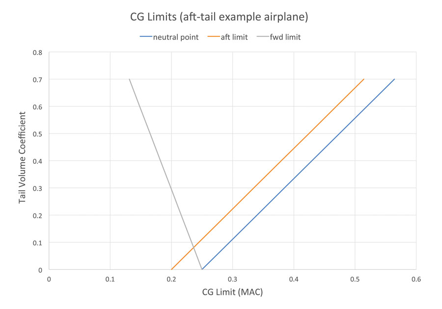
Increasing tail volume coefficient (V) increases the stabilizing influence of the tail. This makes the airplane more stable at any CG position and moves the neutral point (CG position for neutral pitch stability) aft.
The aft CG limit for an airplane is set by a minimum acceptable stability level measured in “static margin” (SM). Static margin is the distance from the CG to the neutral point, divided by the MAC of the wing, and is expressed in %MAC. Once the minimum acceptable SM is set, we know the distance ahead of the neutral point at which the aft CG limit will fall.
At the other end of the CG range, we find that increasing V increases the pitch control power of the airplane. This increased control power makes it possible for the pilot to generate more nose-up moment, and trim the airplane or lift the nosewheel for takeoff at a more forward CG position.
From the above we can see that increasing tail volume moves the forward CG limit forward and the aft CG limit aft, giving the airplane a wider range of allowable CG positions.
Figure 1: Forward CG limit, aft CG limit, and neutral point for an aft-tail airplane as a function of tail volume coefficient.
These effects are illustrated in Figure 1, which plots the forward CG limit, aft CG limit, and neutral point for an example airplane as a function of tail volume coefficient. This plot is referred to as either a “scissors plot” or a “notch plot” in industry.
The scissors plot for an aft-tail airplane illustrates one reason why the aft-tail configuration became standard early and has persisted as the most common aerodynamic configuration. Increasing tail volume has only beneficial effects on stability and control. This means that the configuration is relatively easy to make work, since most longitudinal stability and control issues can be solved by making the tail bigger or lengthening the tail arm, both of which are relatively straightforward things to do. More importantly, changing the tail geometry to improve one CG limit also improves the other, so we do not end up in a situation where we have solved one problem but exacerbated another.
Figure 2: Forward CG limit, aft CG limit, and neutral point for a canard airplane as a function of foreplane volume coefficient.
This is not true of canard configurations. The foreplane of a canard is destabilizing in pitch. Increasing the size of the canard or moving it forward (more negative V) moves the neutral point and the aft CG limit forward. At the same time, it increases the nose-up control power of the configuration, moving the forward CG limit forward as well. An example scissors plot for a canard configuration is shown in Figure 2. Notice that increasing the absolute value of V moves both CG limits forward. They also move apart because the increased nose-up control power moves the forward limit faster than the destabilizing influence moves the aft limit. The allowable CG range gets wider, but the whole CG range moves forward. This phenomenon makes getting a canard airplane to balance properly significantly more difficult. There are enough successful canard airplanes to show that it is possible, but it is much trickier than getting an aft-tail configuration to balance, and it is much harder to adapt a canard configuration to accept changes in its physical CG.







Hallo. I am really impressed with the usefulness and simple step by step guidance which gives Barnaby Wainfan’s articles in the early stage of aircraft design. I am an aircraft engineer, but my specialization is mainly in load computation, structural analysis and strength tests. I have almost forgotten most of flight mechanics. But now i am designing my own single seat high-wing aircraft for pleasure flying and navigation competitions. So i have to learn again how to design an aircraft from aerodynamic point of view. I have difficulties to understand how to draw the “scissors chart” . I quite understand the aft CG limit – it is a derivation of an aircraft moment curve slope by AoA set equal to zero (plus 5% reserve). But what is the front limit? Is that aircraft moment curve in landing configuration expressed through lift coefficient when lift coefficient is set to maximum? Should one include the effect of elevator deflection? If this is truth, required data are not available in the early stage of the design process. Or is there any way around? Thank you.