Most aircraft with electric trim need a controller for proper and safe operation. The homebuilt controller described in this article has all the functions of the fanciest commercial units at less than one-tenth the cost. It uses the one-off construction method described in my May 2009 KITPLANES® article.
Functions
The first job of a controller is to enable the use of dual trim switches, one each for the pilot and the co-pilot. To fit within the control grip, these switches tend to be small, so they should not be required to directly carry the higher currents needed by some trim motors.
The controller should handle two axes: pitch and roll or pitch and yaw. It also must prevent trim runaway, in the case of a stuck or shorted switch or other failure. Various backup and recovery modes need to be available as well. Another function is dual trim speed. Depending on aircraft speed, slower trim movement at cruise and faster change for takeoff and landing are a good design feature. Finally, if your autopilot has autotrim capability, this needs to be integrated into the trim control system.
Circuit Description
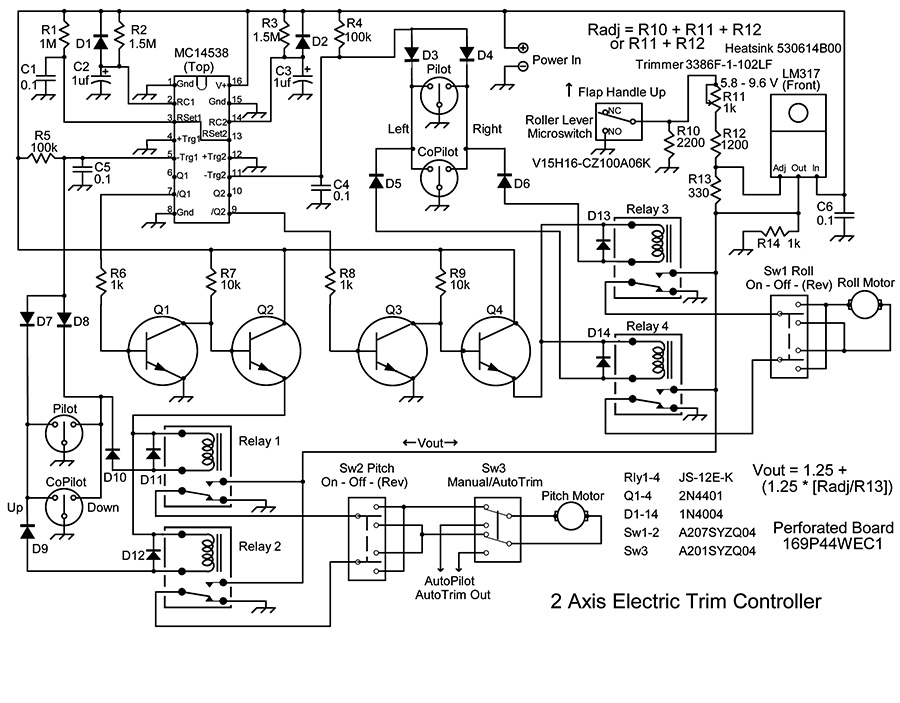
The schematic of the entire circuit is shown in Figure 1. It has four sections: power control for each axis—that’s two of the four—a changeable voltage power supply and external control switches. Let’s look at the pitch-axis section first. The other axis is identical. These details will help troubleshoot any problems as well as help you mix and match circuit elements for other projects.
Figure 1. Author’s dual-axis trim controller design, above, is based on an MC14538 integrated circuit. Other component values aren’t critical, but are listed in bill of materials.
The pitch motor is driven by two relays (Relay 1 and Relay 2), one for each direction of motor travel. Relay 1 is controlled on the ground side by either of the two parallel down-trim switches. The ground side of Relay 2 is controlled by either of the parallel up-trim switches. If one pilot activates the down switch and the other the up switch, then both relays are energized. This causes the motor to be fixed at its current position as both its terminals are then at the same voltage. Eventually, the power side of the relays will time out. Then the trim can’t be reactivated until both trim switches are released.
The positive voltage power side of the two relays is controlled by half of an integrated circuit MC14538 Dual Retriggerable Monostable Multivibrator (whew). The Monostable Multivibrator part of the name means that it generates exactly one pulse when it’s triggered. Retriggerable means if another valid trigger occurs before the end of the pulse, the output pulse is extended by the amount of the original pulse. Thus repeated blipping of a trim switch will cause continuous movement of the motor, interrupted only by the length of the off portion of each blip.
Reviewing Side 1 of the 14538 (the left half on the schematic): RC1 (pin 2) is the timing pin, which determines the length of an output pulse. R2 and C2 multiplied together create a timing constant, in this case 1.5 seconds. 1.5 megohms (R2) times 1 microfarad (C2) equals a total 1.5 seconds, the “mega” cancels the “micro.”
Diode D1 is a protection device for the integrated circuit. It diverts the energy released by C2 when power is removed. Reset 1 (pin 3) overrides any output when reset is low. R1 and C1 form a brief low-reset signal when power is first applied and a high input otherwise. This prevents the 14538 from creating a nuisance pulse when power is first turned on.
This family of devices provides for either a positive or negative edge trigger. One of the benefits of the 14538 compared to the older, more common 4098 or 4528 integrated circuits of identical function is its triggering requirements are much less picky.
R5 is a simple pull-up resistor which puts a high signal on the negative trigger input 1 (pin 5) until one of the trim switches is grounded. This falling voltage triggers the Monostable. C5 prevents a retrigger when the trim switch is released. Switching diodes D7 and D8 combine the grounding signal from either the up or down switches while isolating them (and the relay coils they ground) from each other. This allows one Multivibrator to power both relays. D9 and D10 isolate the relatively low impedance of the relay coils from the negative trigger input. D11 and D12 suppress the spikes generated by the relay coils when power to them is removed.
The controller features adjustable trim speed based on flight configuration. A microswitch on the flap handle senses flap position, increasing trim change rate at slow speeds, decreasing it when the flaps are up.
The positive trigger input 1 (pin 4) is tied to ground to prevent it causing any spurious triggering. The Q output (pin 6) is unused. The negative logic output not-Q (pin 7) feeds the coil driver formed by NPN transistors Q1 and Q2 which are operated as switches. This is the same driver used in my previous article.
High voltage (not-Q off) fed to the base of Q1 turns Q1 on. This pulls current through R7 which drives the base of Q2 down and shuts off current through Q2 and the relay coils. Alternatively, low voltage to the base of Q1 (not-Q on) shuts off Q1, raises the voltage at the base of Q2, which turns on Q2, and powers the relays. When the Monostable times out, the not-Q output returns high and the power to the two coils is cut off.
The coil driver has several benefits. It greatly lowers the load on the integrated circuit output. If a less sensitive relay coil is used, such as with a less expensive or much larger relay, the circuit will still work. It is a general purpose way of driving external loads from almost any integrated circuit output.
The coil driver also provides some extra failure tolerance. Most integrated circuit failures will create a low or no signal at the not-Q output. With this driver circuit, power will then be applied to the relay coils full time, allowing a relay to still be activated by a trim switch.
The dual-speed portion of the controller is an LM317 programmable voltage regulator. Within limits, the voltage out is controlled by the ratio of two resistances, the resistance between the output and adjust pins and the resistance between the adjust pin and ground. As shown in Figure 1, the output voltage formula is Vout = 1.25 + (1.25 * [Radj/Rout]). The adjust leg resistance is either the three resistors in series (R10+R11+R12) or just two when R10 is shorted by the microswitch.
Rout (R13) can be any value roughly between 200 and 1000 ohms. If you don’t have the exact resistors to match, use a different value of R13 to come up with the ratio, and therefore the voltage, you desire.
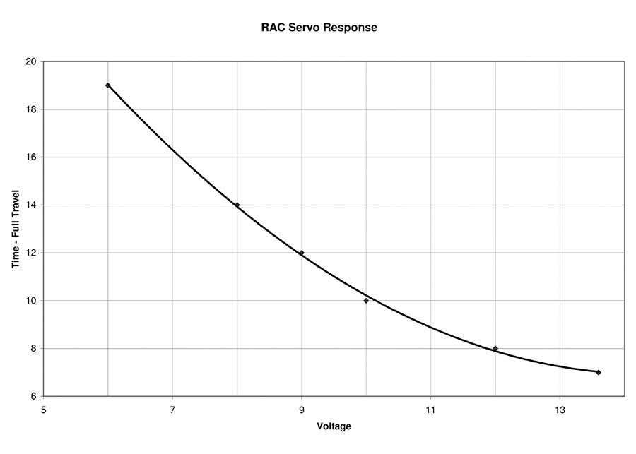
The values shown in the schematic will allow the single turn 1k ohm trimmer (R11) to set the low voltage between 5.8 and 9.6 volts. The Ray Allen Company (RAC) trim motors widely used by homebuilders travel lock to lock in around 7 seconds at 12 volts. At 7 volts, the motor takes about twice as long. Below 6 volts, the motor starts getting cranky. I set my controller low voltage to 7 volts. The LM317 has a minimum 2-volt drop so the maximum Vout will be about 12 volts. Figure 2 graphs the RAC motor speed vs. applied voltage.
Figure 2. The RAC servo response varies with input voltage, allowing faster trim at slow speeds (more input voltage) or more subtle changes at higher airspeeds.
The other parts of the regulator section are C6, a power input filter capacitor and R14, which provides a minimum load for the regulator. Both of these make the output more stable, but could probably be omitted for this application. Also, the heat sink specified is overkill unless you are running significant loads all the time. The RAC motors draw less than 0.2 amps each, so for intermittent use like trim adjustment, the regulator is just loafing.
If you do use a heat sink, be sure to mount the regulator using an insulating shoulder washer and sheet insulator with thermal grease on both sides between the regulator and the sink. The tab on the LM317 is at Vout voltage, so it’s important to keep it insulated and protected from shorts.
The voltage level sent to the trim motors is determined by whether R10 is shorted out by the microswitch or not. The switch is placed somewhere along the flap mechanism so whenever the flaps are deployed, the switch is open. When the flaps are fully up, the switch is closed, shorting out R10. So when taking off or landing with the flaps deployed, you have full power to the trim motors allowing rapid, large trim changes. In cruise, when the flaps are up, the motor speed is slowed, making it easier to command small trim changes.
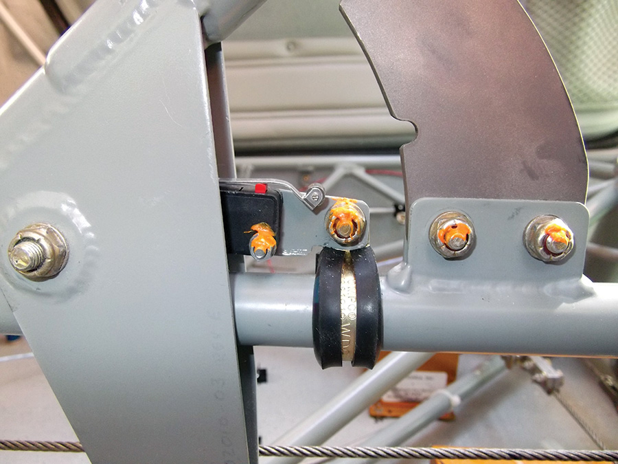
My speed change microswitch is under the flap handle, just forward of its pivot. When the handle is down (flaps up), the switch is closed. As shown in the photo, it’s mounted to a small, flanged piece of aluminum which is Adel-clamped to the tube below the handle.
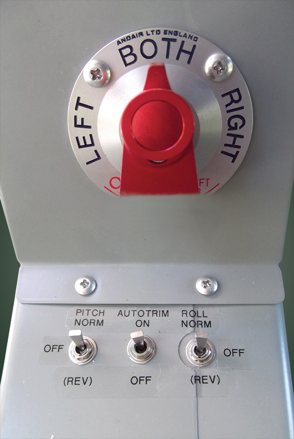
The external switches provide additional functionality. Mine are mounted on the center console of my Sportsman, just ahead of the flap handle. Switches 1 and 2 are the final control for each motor. They have three positions. Center is off, up/forward is normal operation, and down/back is spring loaded and reverses the power connections to the trim motor.
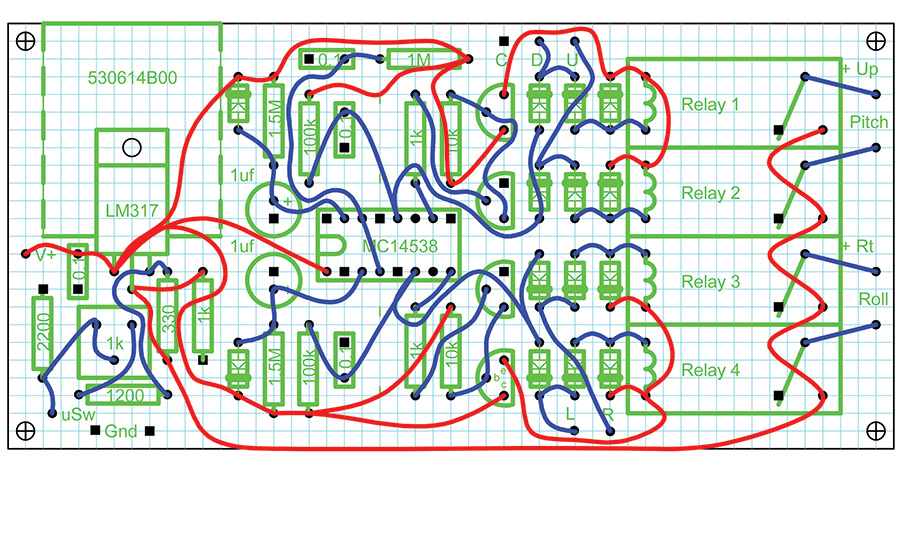
Figure 3. To simplify construction, the controller isn’t built with an etched board, but a single-sided copper board perforated at 0.1-inch intervals. Bus and changeable power supply wiring are shown in red, other wiring is in blue. Topside components are green.
If a trim motor is in runaway, first set the switch to the center position to stop further movement. Then blip the reverse switch repeatedly to return trim to the desired position. If a failure allows movement in only one direction, put the control switch in the center position. Then hold the reverse control on and blip the trim switch for the opposite operating direction. Repeat as needed.
The third switch is used only if you have an autopilot with autotrim capability. It’s a simple, two-position double pole–double throw switch which connects the motor between the manual controller and the autotrim power sources.
The controller is housed in a simple metal project box Shoe-Gooed to the floor under the co-pilot’s seat. Wiring barrier blocks are similarly affixed.
Construction/Options
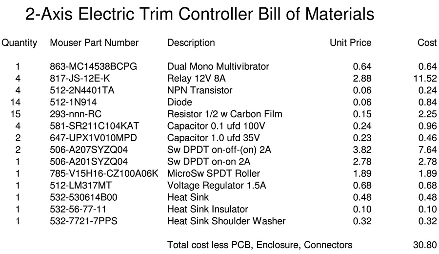
The controller is built on a 2.4 x 5-inch single-sided copper board perforated at 0.1-inch intervals. All the parts are available from Mouser Electronics (www.mouser.com) using the numbers shown in the bill of materials. Except for the integrated circuits, the components are not critical. Capacitor and resistor values can easily be increased or decreased by a factor of three or more. I used half-watt carbon film resistors because they are the lowest cost. The diodes and NPN transistors can be any common, small signal type.
Component placement and wiring are shown in Figure 3. Everything there is bottom view. The bus and the changeable power supply wiring are shown in red, other wiring is in blue. The black dots are insulated leads through the board for components. The black squares are where component leads are soldered to the bottom side copper ground plane. The components on the top side of the board are shown in green.
Note the polarity of the diodes. The band at the end of each points away from the horizontal centerline. After assembly and thorough testing, the bottom is coated with Performix Liquid Tape, available from Walmart. This insulates and improves vibration resistance. See May 2009 KITPLANES® page 43 for more details. If you insist on doing the unneeded extra work of etching a printed circuit board, this layout could be used as a template as it has no wire crossings and allows access to all the grounded terminals.
One of the nice things about building something yourself, whether it’s an electronic box or an entire airplane, is the ability to make changes to suit your personal preferences. For example, the runaway timeout constant on some commercial trim controllers is set at 3 seconds or so. For RAC trim motors, 3 seconds is enough time to travel from near center position all the way to the stop. So I chose a timeout of 1.5 seconds. The extra effort of having to re-toggle a trim switch now and then is well worth the improved safety margin for me.
Another option is circuit robustness. The sensitive coil relays specified consume little power and can switch up to 8 amps DC. The extra dollar in cost for each compared to lesser relays might matter in a commercial product, but not for a homebuilder’s one-off example. As mentioned above, the heat sink used is also much more than needed, but provides an extra margin of comfort. All the coil and capacitor spike-protection diodes are also belt-and-suspenders style design, as is the LM317 input filter capacitor and load resistor.
It’s easy to modify the controller for only one axis. Omit all the components connected to pins 9, 11 and 14, up to and including Q3, Q4, Relay 3, Relay 4 and Switch 1. Connect pin 11 to pin 16. Disconnect pin 13 from pin 3 and reconnect pin 13 to ground.
The wiring diagram looks complex, but there’s not really much to the controller. Components are mounted on a perforated board.
Some changes can be for cosmetic reasons. I have control switches with flattened handles instead of the standard round ones simply because I think they look better. The controller itself is in a standard project minibox placed under the copilot’s seat. It’s connected to the various switches and power with barrier blocks and crimped ring connectors. This makes it easy to reverse polarity of the trim switches and motor power leads as needed to make everything work as intended. The blocks and controller are simply Shoe-Gooed to the fiberglass floor. Just be sure to label and document all the wiring for future reference.
You can save hundreds of dollars and stretch your skills by building your own trim controller.


