Looking back at projects in prior issues of KITPLANES®, I realize I’ve given you a lot of good ideas for circuits without telling you how to actually make them for your own aircraft. This series of articles is going to give you those missing discussions of production rather than the theory and breadboard shots of how the circuits work.
I’ll say right up front it’s going to be tough to condense a class that normally takes 4 hours a week for 16 weeks into a couple of two-page columns. However, I’m going to give it my best shot, so let’s get on with it. We’ll use a redesign of the charger from the Hangar Off Grid (HOG) Program as a real-world example of a project in need of a circuit board.
When I first designed the “little” HOG charger that only keeps the aircraft battery charged, I designed it for the little 1.5-watt solar panel. Upon investigation that this panel would only give me a hundred milliamps or so under the best of conditions, even with a switching regulator that was 95% efficient, I rethought the problem. For the same price I found a source for 5-watt panels that would work just fine with a regulator and less expensive components. So here we go with the redesign of the regulator: Out with the switching regulator. Out with the relatively expensive inductor, one of the Schottky diodes and the smaller, less expensive capacitors. In with a relatively new linear regulator made just for this application.
In a nutshell, here was the problem: The switcher required what we call “headroom.” That is, the input voltage needed to be between 2 and 3 volts before the output kicked in. If we needed to have 13.6 volts output for the battery, the input voltage from the solar cell needed to be north of 15–16 volts and that just didn’t happen until mid-morning and only lasted until mid-afternoon in the summertime. Our battery only got 13.6 volts at 100 mA (1.4 watts) from 10 a.m. until 4 p.m. (6 hours), which translates to 8 watt-hours. That would hold the battery up just barely—until a cloudy day came along or winter set in and it went downhill (way downhill) from there.
The new little linear regulator requires a bit less than a volt of headroom (or “low dropout”), so we got almost double the amp-hours of the switching design. That and the cost of the parts was cut nearly in half. Now we’ve got an idea of what we want to do. How do we translate that idea into hardware?
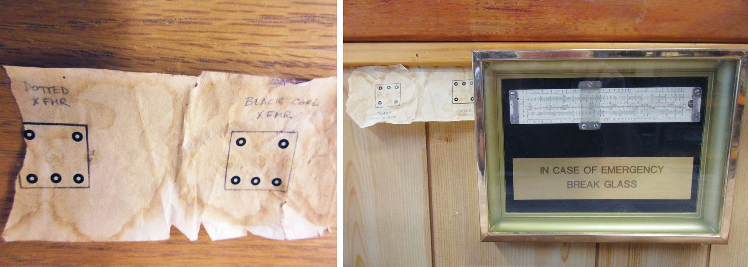
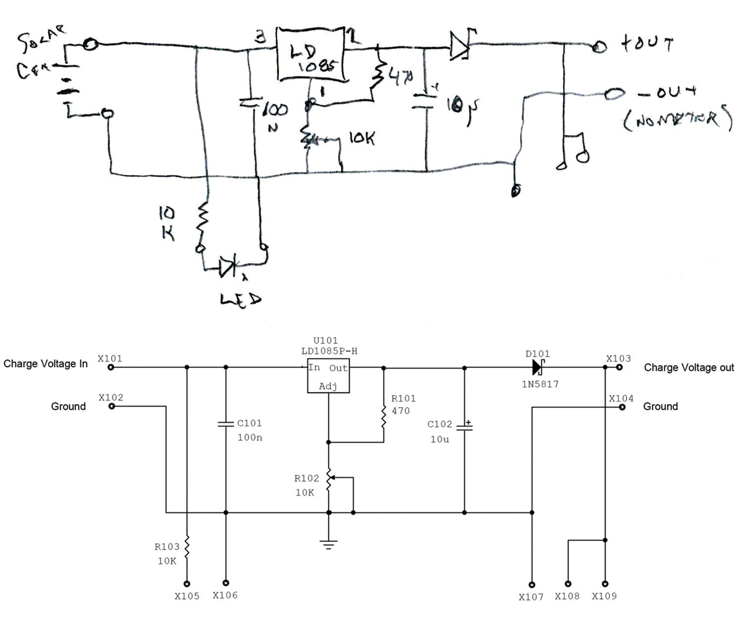
- We start out with a hand sketch on paper (use erasable pencil) of what we want to do in schematic format.
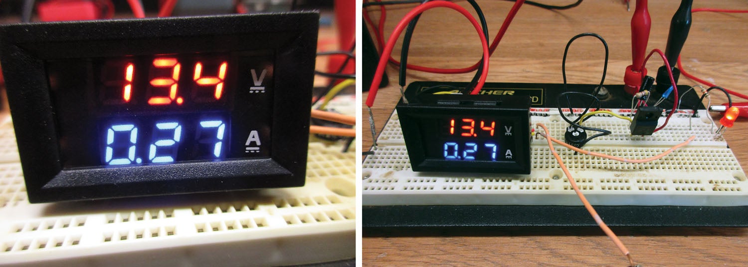
- We breadboard up the design and test it, first with a lab power supply and resistive load just to see if it is doing what we think it will do.
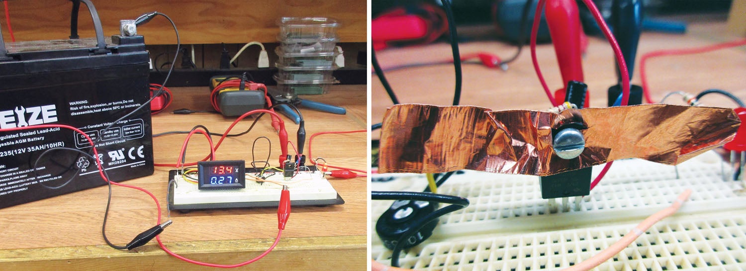
- We then use the real power source (solar cell or array) and the real load (a spare 35-amp-hour AGM battery or the battery out of the airplane). We measure the current at the start of charge (9 a.m.), at the peak of charge (about noon) and at the end of charge (4 p.m.). We note the following currents, respectively: 50 mA, 365 mA, and 40 mA. Just like we predicted. We also note that the currents jump quite quickly to over 100 mA half an hour after start and half an hour before end. Just like we hoped they would.
So, we now do one of two things…pat ourselves on the back and say “good job” to ourselves or we look in the mirror and remember that even a blind pig finds an acorn every now and then.
Either way, we can’t just use that crude breadboard as the final form factor for a finished project to put in the hangar forevermore for a few reasons, not the least of which is that the breadboard wasn’t meant to be in a hostile environment that is freezing in the winter, broiling in the summer and full of dust, hydraulic fluid, grease and everything else associated with maintaining an airplane. Not to mention that the components are held onto that breadboard with metal spring strips that will slowly lose their spring over time and the circuit will eventually become intermittent.
Finally, I’m sure like most of us, you keep a current drawing and modification log for the airplane and everything associated with it. A crude hand-drawn pencil schematic is better than nothing, but not by much.
Where is all this leading us? Eventually I want this circuit/project soldered together on a PC board and inside of a decent enclosure so I can rely on it to give me long and reliable service. To do that properly requires that I come up with some software to let me automate the production of both a decent schematic and some way of translating that to a PC board.
A very long time ago (1962), a very young engineer-in-training made his living by laying out PC boards with state-of-the art techniques called “tape and donuts.” That is, on a thin sheet of clear plastic, we made PC artwork with lines made out of blue and red crepe tape and pads for components with black crepe circles with holes in the middle for drilling component leads. A very expensive camera with very expensive blue and red rejection filters gave us the bottom and top negative films to let us use either a silkscreen process or a photographic process to make the PC boards.
Today we draw both the schematic and accompanying layout programs on a computer screen, reduce that computer screen to digital files, email the files to a PC board shop and, in a week or so, you have the boards in your hands via mail. And, you are the first human being to touch those boards, everything else (layout, etching, drilling, packaging, mailing) is done by machine.
The problem reduces itself to finding a program that lets you do that schematic and PC board layout process. There are good programs that are free and some not so good programs that cost thousands. Your homework for this month is to pick from what I think are the best of the best freebies. Here is a place to start, which lists 10 of the schematic/layout free programs. Here is what to watch for:
- Some PCB manufacturers offer a really great PCB program; the catch is that they force you to use their company to manufacture the boards. Look for programs that say “Outputs are Gerber and NC Drill.”
- Look to see how hard it is to create new parts. Sure, they have 10,000 parts in their library, but the odds of you using their parts are slim. Look to see if the LD 1085 or 1085P that we are using is in the library, then figure out how much hassle it is for you to make that part.
Next month we’ll explore how to use your chosen software to make the digital files and then we go into some detail on how to translate that software into hardware (the PC board itself). Until then, stay safe…and stay tuned.


s")


![Humberd and his daughter using the 701 for some farm duty transportation. [All Images Credited to Jon Humberd]](https://www.kitplanes.com/wp-content/uploads/2026/05/1-3.jpg?w=324&h=160&crop=1 "Builder’s Spotlight")

