
Way back in 1990, when I had brown hair and was a wee lad of 47, I did one of my first KITPLANES® articles on using a diode as a temperature sensor. Sixteen years later, in 2006, I did a follow-up article on how to use a cheap multimeter as a digital thermometer using the diode article as the basis for sensing temperature.
Now, only 14 years later, we are going to do an update with stuff we’ve learned and a few more goodies we’ve managed to put together for the project.
There are very few instruments that have been on my bench on a continuing basis for a long time. I use a Heathkit solid-state multimeter that I built in high school (circa 1960). My primary oscilloscope is my first purchase when I started RST Engineering back in 1973, and my soldering iron has been with me from that same year. And my trusty temperature gauge still uses the 1990 diode sensor and 2006 circuit from KITPLANES®, stoned spider construction and all. Everything else I use on a regular or semi-regular basis has been acquired in the last 15 years.
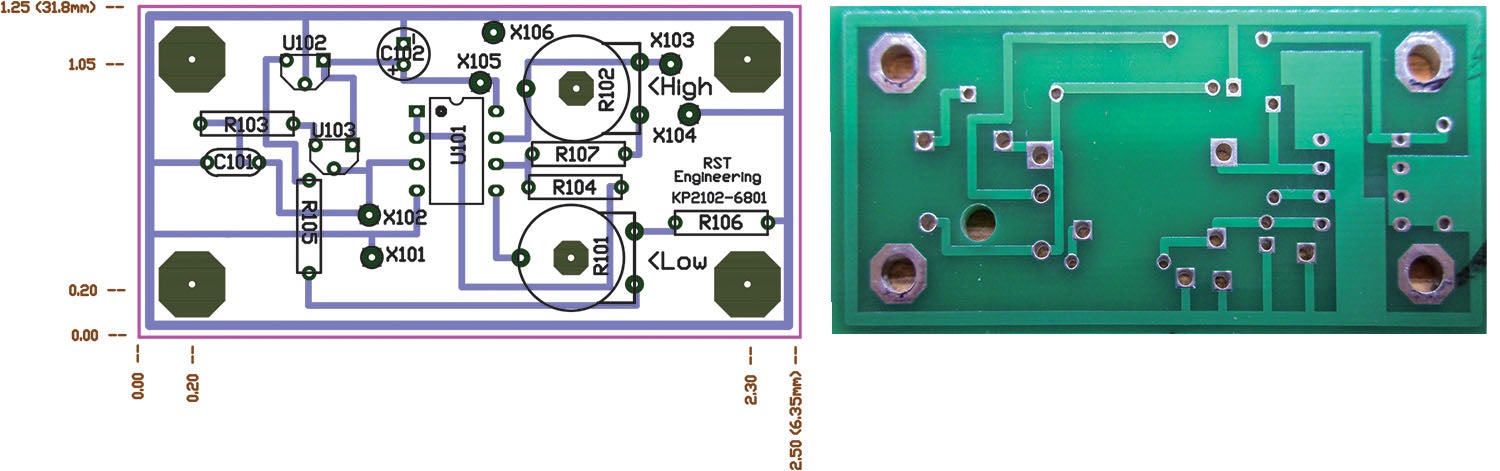
My personal temperature circuit has been revised, revised, and revised again to give me better accuracy and ease of use. The sensor has the glass diode I specified in 1990 replaced with a newer epoxy diode that doesn’t crack when exposed to very hot temperatures and then cooled or hammered. There are also better ways with more modern ICs that increase performance while decreasing parts count and cost. I finally made a PC board so that the circuit doesn’t resemble a stoned spider’s web, and it fits into a box that is a bit more respectable than having alligator clip leads all over the place. Finally, I figured out a really simple way of operating from either a 9-volt battery or a 12-volt system without frying the battery if I forget to take it off before applying the 12 volts.
I have decided to offer at my cost the first 10 PC boards and all the parts you need to make one of these improved thermometers for your own toolbox. The only caveat is that you have to do some drilling of small holes on the plastic chassis that hold all this stuff together. Plus pay the postage. Details at www.rstengineering.com.
For those of you who did not keep your copy of the April 1990 and October 2006 issue of KITPLANES®, let me do a brief summary of how this all works.
We have long said that common diodes made from silicon have an approximate forward voltage of roughly half a volt (0.5 volts or 500 millivolts) at some reasonable current level. We also noted that this voltage varies precisely with temperature, straight line at 1.38 millivolts per degree Fahrenheit. In this ensuing quarter of a century I’ve also found that the new versions of welded epoxy body diodes (like the hefty 1N4000 series) do not disassemble themselves like the soldered glass body (1N4148 series of diodes) we used in the 1990 design and can thus withstand far more heat than the glass diodes. To boot, the epoxy bodies don’t crack like the glass bodies if they are subjected to fairly rapid changes in temperature or are subjected to physical stress (like a misplaced hammer blow).

One more refinement is to replace the Zener diode, op-amp and resistor-diode quasi-constant current circuit with a true current source that depends on a temperature-compensated band-gap reference and not six separate components that can vary with workroom temperature.
Since I got rid of one section of the 2006 op-amp, the only reason I used the fourth section of a quad op-amp in 2006 was as a buffer, which wasn’t needed at all, but it was easier than just letting it sit there and do nothing. That let me use an eight-pin op-amp rather than a 14-pin device, which made the circuit roughly half the size of the 2006 version.
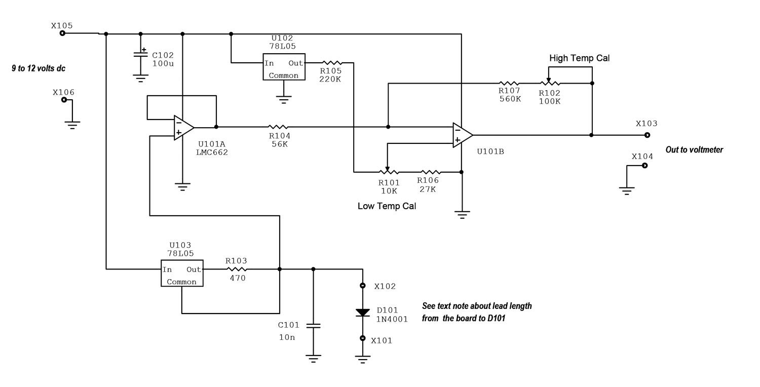
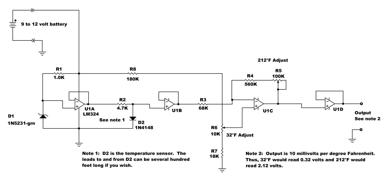
Shown are two circuits. First above is the 2006 version and below is the 2021 version. Note the relative simplicity of the current version. These are the major changes that I’ve made:
- The integrated circuit did away with the relatively large 14-pin integrated circuit for the smaller eight-pin device.
- The current source for the temperature sensor (D101) is the temperature stabilized band-gap reference in U102 instead of the fairly inaccurate medium value resistor current source.
- The 32° meter set resistor R104 is being fed from a 5-volt regulated source. This provides better calibration stability than an unregulated source feeding this adjustment.
- The input impedances of the chosen CMOS LMC662 op-amp are several decades higher than the original bipolar LM324, loading the sensor and the rest of the circuitry to near zero.
- We have somewhat cleverly used two 9-volt battery clips and color-coded wires to prevent using a 12-volt source while a 9-volt battery is connected. The old arrangement provided much excitement when the 3-amp 12-volt power supply tried to charge the 9-volt battery I forgot about.
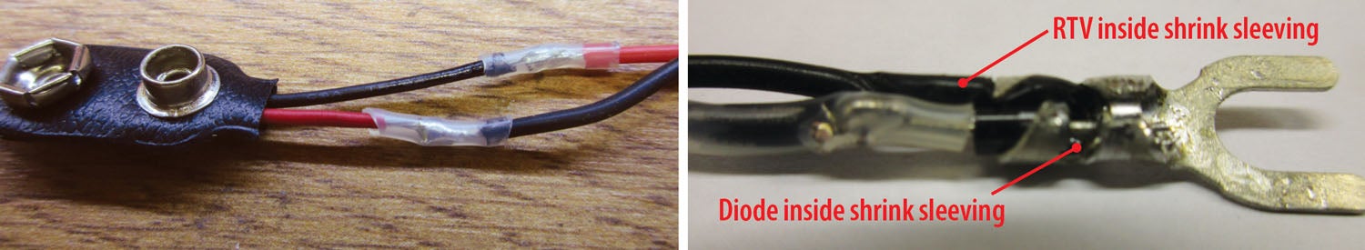
- The sense diode is now connected to the outside world with an easily removed connector so that the sense diode and the remaining circuit may be stored in a much smaller container.
- You can have as many sensors as you wish, some with short wires for bench use and others with long wires for monitoring such things as engine parameters from inside the cabin (up to about 300 feet long with no errors). Please note that for this option you have to match the diodes at room temperature for forward voltage at the same forward current within one degree on the voltmeter.
- The small glass diode had a nasty tendency to crack when taken above 200° F. While the 1N4001 has a 200° F rating also, I have used it for cylinder head measurements up to 400° F with no problems. This is experimental, your mileage may vary and your diode may go up in a puff of smoke (or worse).
- The PC board takes this device out of the lab curiosity and into the realm of a real instrument that can be relied on in the shop.
- The same thing can be said of the chassis. No longer are we stringing things around with alligator clips, but real connectors and real enclosures.
Next month (unless the fall weather turns real nasty) more on the hangar solar power HOG series. Until then…Stay tuned…


Jim
I am interested in obtaining the kit of parts for the thermometerdescribed in the December 17 online article. I could not find it in the link to your site. How do I order and pay?
Merry Christmas &Happy New Year.
Kim Jones
Comments are closed.