I like to keep my columns contiguous. That is, when I write about two things I like to have them somehow relate to one another. Im trying to find that thread between these two subjects, and the only thing that I find they have in common is that they are wired together. I guess thats close enough.
Products have been brought to market that purport to be the main electrical system junction box for an airplane. Nice looking, but the sticker shock is a bit much. We can do it for much less. Then we can make the connectors for this junction box color-coded so that you can keep the goes-intas and goes-outas straight, plus have an inexpensive way of making labels for the various connectors.
Whats in the Box?
Lets attack the junction box first. What do we want in this box? Wed like a way of bringing in primary power from the battery bus and distributing it to the various radios, instruments, lights and other electrical power loads of the airplane. And how about some of those newfangled solid-state fuses that reset themselves when the fault is removed? Wires to on and fault LED pilot lights?
Well discuss the goes-inta and goes-outa connectors in a bit. First, lets presume you have figured out what you want to do with outputs. The inputs are simple: battery bus voltage and airframe ground. No problem. The outputs should be relatively low power such as radios, instruments, nav lights, strobes and the like. The heavy amp outputs like landing lights, alternator outputs, starters and all draw lots of ampicity and don’t go through this box. You might call this the delicate electrics box. About the heaviest currents I want running through this box are 5- to 10-amp circuits.
Ill say this one more time, and then again as long as Im writing columns. Get yourself a good computer-drafting program. The one I prefer for mechanical drawings is Autosketch (Autocad), and for schematics my chosen program is Circuitmaker 2000. Neither one is in current production, so you will have to Google them to find an obsolete copy on the Internet. And neither is trivially simple to learn, but once you learn, you have a tool every bit as basic and easy to use as a screwdriver. Draw your box schematic in the drafting program. I have done condition inspections on more homebuilts than I care to count where the electrical system drawings (sometimes literally) are in pencil on supermarket shopping bags.
Inside the box we have terminal strips for all inputs and outputs. We are using the Cinch-Jones series 140 that we have come to love over the last 30 years along with the crunch terminals that were mentioned in last months column.
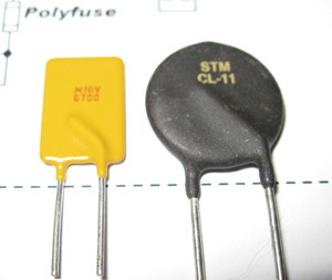
The left device is a polymer fuse; the right device is an inrush current limiter. They are both made with the same chemicals, but one has more of the heat polymer while the other has more of the cool polymer.
Plastastic
Let’s have a little discussion of these plastic fuses we’ll use. Im no chemist, but as I understand it, these fuses are made of two differing types of plastic polymer. One is a cold polymer, and one is a hot polymer. By adjusting the ratio of the two plastics, you can have a material that is a near dead short until it gets hot (a fuse) or a near open until it gets hot (an inrush current limiter). By adjusting the ratio just so, you can have a polymer that gets hot at a particular current level. Our old friend the Mouser catalog shows that the Raychem series of PolySwitches can have fusing currents from 50 mA (0.05 amps) in the RXE series to 14 amps in the RGE series. You can pretty well have any fusing current you wish between these two limits.
Picking a fuse value is something of an art. With regular circuit breakers and glass-tube fuses you generally pick a fuse that is 20% to 25% over what the maximum current of your device is going to draw. Because Polyfuses take a little longer to break, you want no more than 5% to 10% headroom over the protected device. For example, if you have a radio that draws 2 amps on receive and 4.5 amps on transmit with all the lights and bells on, you would pick no more than a 5-amp resettable fuse, and Id probably go with a 4-amp fuse. Why? Because a 4-amp fuse has an 8-amp trip rating, meaning that you have to draw 8 amps to cause it to trip instantaneously (or nearly so). With a 5-amp radio in the transmit mode, it may take up to 5 minutes to get hot enough to trip the fuse. Anyone who is chattering on the radio for 5 minutes deserves to be cut off. And it performs as a dandy stuck-mic indicator.
With what we learned last month about indicators, loads and fuses, we can draw our circuit as shown. Here all the raw power comes in through J1/P1 through a 20-amp (or less if your total draw is less) breaker. It comes in through pins 7 to 12 (5 amps maximum per pin) so we have six pins providing + supply and six pins (1 to 6) providing airframe ground.
The fuse/indicator circuit itself requires only two of the terminal blocks eight stations, so we can get four radios or instruments per terminal block. Each radio goes out of the junction box on a six-pin nylon connector.
Ah, yes, the nylon connector. The consensus is that aircraft use expensive connectors, gold-plated pins and hundred-dollar crimp/assembly tools. Nope.
The 03-06 series of Molex connectors (look at: www.molex.com/pdm_docs/ps/PS-02-06.pdf) go for about 5 cents a hole for both plugs and receptacles (i.e., the nylon shell goes for about 60 cents for a 12-pin connector), and the pin is also about a nickel apiece for both male and female. As they come from the factory they look like they belong in a washing machine, and thats good, because thats where 99% of them are headed. How do we make them look aircraft quality? The easiest way is to dye them so that they don’t have that milky white appearance.

The schematic.
To Dye For
I called the Molex factory to ask how the special coloring on its products was done, and the old geezer running the line said, At home, I use RIT and throw in a tablespoon per gallon of baking soda. He was right. Two packages of dye in a gallon of water plus a tablespoon of baking soda, and the nylon will take on any color-yellow, green, red, black.

To the left are two freemount cable connectors; the two on the right have ears for chassis mounting.
We started off using a crockpot, but soon found that the sharp edges needed for the pin flanges to take a grip hold were rounding off in the hot water bath. So we started leaving them for one to two days in room temperature water. We got the deep colors, but didn’t get any rounded edges, so thats how we do it today.
How to fasten nylon connectors to the metal chassis? On the web page referenced above, you will see that this series of connectors comes in two styles: free hanging and panel mount. The panel-mount type has a couple of ears that are notched to fit into a rectangular hole in the chassis. What size rectangular hole? See dimensions A and B in the specifications. I drill a round hole and use what is commonly referred to as a nibbler tool to cut the rectangular hole.
As for the crimp tool for the pins, its $15 or so from any Waldom/Molex dealer. Heres a hint. Most of the time I don’t recommend soldering crimped connections, but on these tiny pins I do-just a tiny bit of solder where the wire is crimped onto the pin. Be sure that the back crimp gets most of the insulation so that the whole pin assembly is well insulated from the outside world. You have your choice of tin or gold plate. I use the tin. When you mate a tin male pin with a tin female pin, they squish into one another, and you get really good metal-to-metal contact. Besides, tin is cheaper.
A friend of mine owns an automobile junkyard. He’s going to pull off a couple of sensors that cars use for smog control, speed control and a few other things. I’ll take them and see if somehow we can bend them around to make interesting goodies for our airplanes. Stay tuned.


