We are back with our old friend the AGM (absorbent glass mat) aircraft battery. This is a relatively new player in the lead-acid battery game and is characterized by a completely sealed battery with the acid electrolyte contained in a polypropylene glass fiber mat. This construction does not allow water vapor to escape from the battery and thus eliminates the servicing of the battery with water every so often. It is truly sealed for the life of the battery.
As with all batteries, the AGM variety does not like to sit for extended periods (say, over the winter) without having some tender love and care applied, most often as a charging current to keep the battery topped up. Letting it sit all winter (or for any period of time measured in fractions of a year) is a sure way of shortening the life of the battery. In some cases where it sits for nearly a year, the battery may appear completely dead.
To the rescue comes section 13.c. of the Concorde Instructions for Continued Airworthiness Maintenance Manual (ICAMM) that comes with every new Concorde AGM battery. I suggest that you keep this, along with the airplane owner-operator manual, with your aircrafts service records and related literature. These manuals contain a world of data that you just wont find anywhere else.
At any rate, section 13.c. uses a conditioning procedure unlike anything Ive ever seen before regarding aircraft batteries. The procedure calls for loading the battery down until the battery voltage reaches 9 volts and then recharging the battery to 14 volts (please read the manual, as there are caveats to both of these numbers).
How do we load down the battery? The ICAMM says to load the battery down at a rate of C1 until the battery voltage goes down to 9 volts. What is C1? C1 is the rated battery capacity for a 1-hour discharge. If you look at the common 25-ah (amp-hour) and 35-ah batteries that most of us use in our aircraft, C1 is either 25 or 35 amperes, depending on which size battery you have. And here is where I depart from the wizards at Concorde. I used a landing light to run the battery down the first time I tried this idea, and the battery got hotter than the devil.
Hot in my vocabulary translates to stress, so I called the aforementioned wizards back when I was doing the AGM battery charger (KITPLANES March 2004) and asked a lot of questions. Turns out that it doesn’t really matter to the battery how you get to 9 volts; the important thing is getting there. So in direct contradiction to the ICAMM (a contradiction that I would never, ever do for a Cessna), I chose to discharge the battery at a rate of about an ampere. This keeps things cool (except for the load resistors) and stress-free.
Charged Up
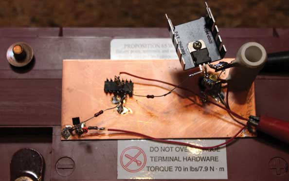
I freely admit to doing a stupid thing every now and again. The last time I tried this technique I put the load resistors onto the battery and promptly got involved with another project. When it finally occurred to me a few days later that perhaps I should look at how the discharge was proceeding, the battery was a flat zero volts. No, I don’t mean a volt or two. A digital voltmeter across the battery read 0.00 volts. Oops. It took me the better part of a week of fussin and fumin with the battery to get it to hold a charge, but that battery never did work well again. That was a $300 mistake on my part. I told myself that this sort of brain burp would not happen again, hence this article on a circuit that will let the battery discharge to 9 volts and then automatically cut the load off of the battery.
Let me take a little side trip for a minute. Ive been asked more than once why my favorite voltage reference diode is a 5-volt diode. Without a graduate seminar in solid-state devices, a zener diode below 4 volts has a negative temperature characteristic (zener voltage goes down when temperature goes up), and above 6 volts the zener has a positive temperature characteristic (zener voltage goes up when temperature goes up). Halfway in between (5 volts), the negative and positive temperature coefficients balance out, and the 5-volt zener voltage stays relatively constant no matter the room temperature.
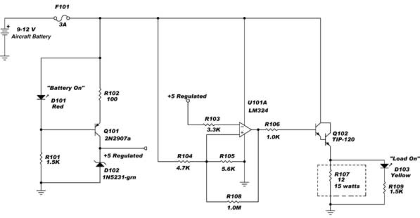
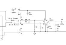
The schematic.
Circuits Circus
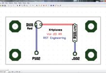
With that out of the way, a short discussion of the circuit is in order. Q101 and the associated passive components form a 10-milliampere constant current source for D102, the 5-volt zener regulator diode. While I sometimes use regular silicon diodes for D101, this time I decided to use a Weir two-fer to give us not only a fairly well-regulated current-set voltage but an on-off light as well. The voltage across D101 remains fairly constant at 1.6 volts over a wide range of currents through D101. The current through D101 varies from 7 mA with a charged 12-volt battery to 5 mA with a 9-volt discharged battery. If this voltage remains a constant 1.6 volts (as it will), then the voltage across R102 will be 1 volt no matter what the battery voltage is. If I want 10 mA to flow in both the emitter and collector, a 100-ohm resistor at R102 will force the current through zener D102 to be a constant 10 mA for any battery voltage from 12 to 9 volts.
The actual load is R107. This can be any combination of power resistors that add up to 12 ohms, either all series, all parallel or some goofy combination of series-parallel. Note that the combination will be dissipating 12 watts with a battery voltage of 12 volts, dropping to about 7 watts when the battery voltage drops to 9 volts. Q102 is what is called a Darlington transistor with a current gain of about 1000, compared to a normal power transistor with a current gain of about 75 to 100. This lets the comparator loaf along; when the voltage is above 9 volts, the combination of R104-105 keeps the (+) non-inverting input above 5 volts. When the voltage drops below 9 volts, the bias from the +5 volt regulated supply through R103 to the (-) inverting input drops the output voltage to zero, turns off Q102 and removes load R107 from the battery.
A caveat: Keep the power transistor and power resistor away from the zener regulator diode and the constant current source. We designed them to be relatively insensitive to temperature changes, but there is no use stressing the design. Keep the regulator and current source as close to room temperature as you can.
Pretty cool, eh? You will have a practically new battery for about $10 in parts. Oh, you want to use the Concorde recommended equipment? Mostly, its in the $500 to $1000 range.
Ill bet you noticed that I used a four-section op-amp but wired to only one section of it. What are we to do with the other three sections? The second part of the conditioning process, charging the battery back to 14.1 volts, will use a couple of those unused sections…next month. Stay tuned.


