
The whip antenna in the center of a 4-foot x 4-foot aluminum ground plane.
Some of our more frugal brethren and sistren spend their whole homebuilding budget on the airframe and engine and have very few nickels and dimes left over for the instruments and radios. One place they try and save is by foregoing the really pretty ($215) fiberglass broadband com antenna in favor of the relatively inexpensive ($75) stainless steel narrowband whip.
I can completely understand this. After all, there isn’t that much difference between the performance of these two antenna types. Or is there?
The Boss (Editor Paul Dye) said that some of his frugal friends were having some trouble with their whizbang electronic gauges and instruments with unwanted blinking lights when the pilot hit the “transmit” button on their radio. Mostly, according to Paul, these were metal ships out of Van’s Air Force using the aforementioned narrowband whips.
There are a few avenues we can experiment with to see if we can stop the light show during transmit. We can look at some stuff having to do with antennas, and then we can investigate a few tricks using capacitors to shuffle some of that transmit energy away from the lights.
Let’s talk about the antenna. Those good fiberglass whips keep the transmit energy (RF) completely contained inside the coaxial feed line (coax) all the way from the radio through the skin of the airplane and into the antenna. The steel whip, on the other hand, requires that the center conductor of the coax be connected to the antenna inside the fuselage skin. While there is a very short distance between the antenna connector terminal and the antenna itself, the amount of coax center conductor exposed to make this connection is a part of the antenna and radiates inside of the fuselage. This RF can bounce around inside the metal fuselage until it finds a home inside one of those gauges and instruments where it can trigger those little lights into dancing around.

The author taking VSWR readings on the whip antenna/ground plane.
There is another phenomenon attached to the narrowband whip. It is called “reflection.” Or, as those of you who have been with us the past few months now know it, “VSWR.” VSWR, as we found out, reflects a part of the transmitter power back down the coax into the radio. If that was as far as it went, that wouldn’t be a problem. Unfortunately, a part of that reflected power comes back on the outside of the radio coax and radiates that power into the inside of the airframe with the same blinking-light syndrome.

The ground plane view from the top. (VSWR meter in lower left corner.)
We can solve these problems, or at least alleviate them.
First, the word short should be the watchword for everything we do with RF. Long wire loops are anathema at RF. In particular, a long center conductor or a long shield connection between coax and antenna connections is a real bad thing. How short is short? No more than 0.75-inch of center conductor or braid between coax and antenna and 0.5-inch is preferable. That long coax center conductor makes a real nice antenna radiating power inside of the fuselage.
I ran a test on one of these whip antennas1 and found that the VSWR was between 2 and 3 at the band edges. The test was done using a scrap of 4-foot x 4-foot plywood covered with alu-minum foil as the ground plane (which approximates what an RV-6 airframe typically would look like to the antenna). This amount of VSWR allows between 10 and 25% of the power to “come back down the line.”
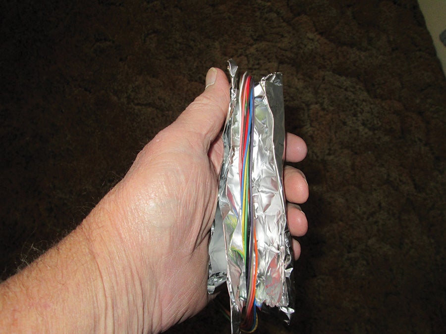
A length of aluminum foil slid over a bundle of wires going to a device will generally show whether it is the wiring or some other method of interference that is causing a problem with the device. Using the foil, wire by wire, will then pinpoint the offending wire. [Note—the aluminum shield was opened to show the wires inside. The test is done by completely shielding the wire(s).]
As we said, most of this power will come back down the center conductor, but a significant fraction will travel down the outside of the shield braid and be radiated into the fuselage. Our problem is to figure out how to get this RF off the outside of the coax braid before it gets a chance to radiate.
Let’s divert for a while before we solve this problem. It is true that iron has some particularly useful properties when it comes to electronics. In particular, it can concentrate an electrical signal to flow through itself rather than air. You’ve seen the phenomenon before…a coil of wire on one side of an iron core and a coil of wire on the other side of the same core makes a transformer. Alternating current on one coil induces a voltage in the other coil through the iron core. This happens with almost zero of the power flowing through the air…it all flows through the iron and thus worketh the transformer.
This doesn’t work very well as we climb up in frequency. In particular, at RF, a solid iron core provides nearly zero power transfer. However, if we grind that iron up into powder, mix it with a binder (like epoxy or glue) and press it into shape, it readily conducts a relatively high frequency electric current. Even better, if we choose a compound of iron and carbon (and iron oxide and other trace metals), we can stretch that frequency range well into the RF range, right where we need it.

Toroids.
There are a dozen different mixes used for these “ferrites.” And they can be pressed into nearly any shape that you would like. One particular shape is called a “toroid” (TOW-royed), which is the Lower Slobbovian word meaning “doughnut”. Yep, little ferrite donuts. And this helps us how?
If we slip one of those little donuts over the coax, the RF flowing on the outside of the coax will travel into the donut and not find a way out…another coil to transfer the power into. So it will continue round and round inside the toroid until the losses in the toroid convert all that power into heat. If we slip another toroid onto the coax, whatever the first toroid didn’t get the second one will, and so on. Two toroids is kill. Three toroids is overkill. The problem is to find toroids specifically designed for this frequency range that just barely fit over the coax.
Micrometals has a particularly nice little toroid called a T37-17 that just barely fits over RG-58 cable and has a very high quality rating in the middle of the aircraft com/nav band. If you are using a different diameter coax, the first number (T37) gives the size and 17 is the iron “mix” that is perfect for this frequency range. You can find 17 mix on the Internet in lots of different sizes for roughly half a buck per toroid. Use two or three per antenna, your choice.

Long leads at the antenna end of the coax will cause problems.
Now let’s turn our attention to another way that RF can get into your little lights. This is called “conducted radiation,” or radiation coming in on the wires you use to connect your electronic device to the power and signal circuits of the aircraft. It just plain travels down the wire and gets into the innards since most wires don’t have any way of preventing it.
The brute force way is to put a little tiny toroid onto each wire going into and out of your gizmo, but that is really a crude way of fixing the problem. The classic “homebrew” way of finding out which wire(s) are the offenders is to take a 6-inch square of aluminum foil, curl it into your hand, and slide it up and down each wire until the light stops blinking. Now take a capacitor with very short leads (see next paragraph) from this wire to chassis ground right where it goes into the unit, or just after where it goes into the unit—directly to chassis ground. Connecting it down the wire or at the transducer or power supply will have absolutely no chance of solving the problem permanently.
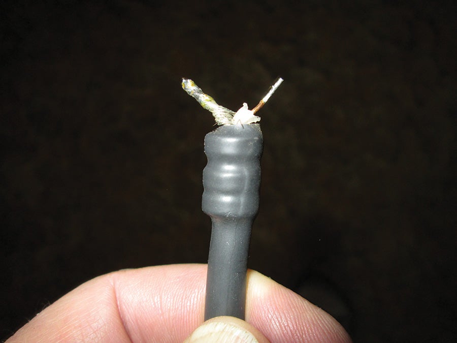
Short leads will do much to eliminate unwanted interference. The three little “bumps” under the black shrink sleeving are the toroids, right where they will do the most good. Note: short leads mean that you will have to be extra careful not to let the shield braid (on the left) come in contact with the coax center conductor (on the right). An ohmmeter is your friend here.
It is true that where a capacitor and inductor are “series resonant,” it will be a dead short at the frequency of resonance. Without going into the theory of resonance too deeply, let me just tell you that a round straight wire of the diameter used on most small disk ceramic capacitors has a self-inductance of about 20 nanohenries per inch. If I allow half an inch on both sides of the capacitor (remember, folks, that’s half an inch on both sides), then the problem is to find a capacitor that is resonant with these lead lengths in the aircraft com band. I did the math for you. It is 100 picofarads, but anything from 68 to 150 ought to work for you.
Please note…these techniques are not unique to Van’s airplanes, metal airplanes, fabric airplanes, or plastic airplanes. The principles apply to any RF problem in any field, aircraft or no.
See you next month…

![]()
Jim Weir s the chief avioniker at RST Engineering. He answers avionics questions in the Internet newsgroup rec.aviation.homebuilt. His new wife Cyndi was his high school sweetheart 50 years ago and now she keeps Jim from making stupid blunders in spelling and grammar. Check out www.rst-engr.com/kitplanes for previous articles and supplements.


