Actually, when they are on super-sale they are only $5, but I didn’t want to give you false hope. Yes, the airplane division of Harbor Freight sells a perfectly good multimeter (voltmeter-ammeter, ohmmeter, diode, transistor, and small battery tester) for this amount. Any day of the week. As many as you want.
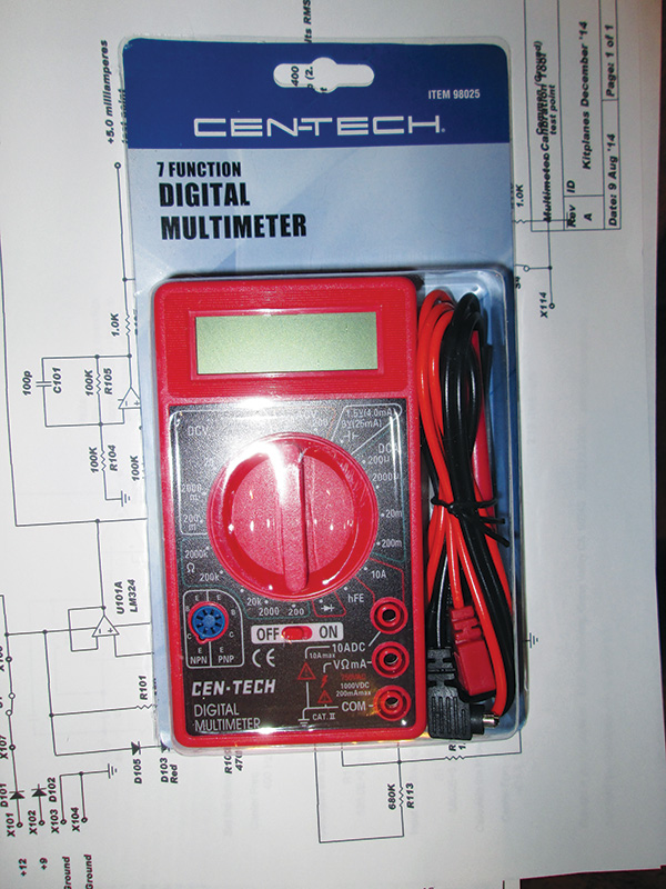
Yes, you can buy a perfectly good multimeter from Harbor Freight for less than $10, but it makes sense to check its accuracy with the KITPLANES® Multimeter Test Box.
200 millivolts (0.2 volts) full scale to 1000 volts full scale. 200 microamps to 10 amps full scale. 6 resistance scales from 200 ohms to 2 Megohms full scale. Transistor beta (current gain) up to 1000. Diode forward voltage and indication of polarity.
But wait, you say—you want more? For another dollar they will sell you the same meter with a backlight so you can work under the panel in the dark.
As with all good, inexpensive things, inexpensive meters like this can and will fail. The failure rate is in direct proportion to how badly you need to make the measurement and how tight time is to get the airplane fixed and in the air. The problem with a “do-all” instrument like this is that you really never know if it is a broken airplane giving you an improper reading, or a broken multimeter giving you an incorrect indication.
Enter the world of the $10 KITPLANES® Multimeter Test Box. Actually it is an “any multimeter” test box, all the way from the lab-grade $1000 HP to this $5–10 Harbor Freight wonder—and anything in between.
To do a really proper test box, you would need one known and calibrated test point for each range of the multimeter. To do that job with a $10 test box (especially if we want it to run from a 9-volt battery) is well-nigh impossible. The good news is that these cheapie meters generally fail one complete function and not just one range. That is, if the voltmeter is good on the 20-volt range, it is generally good over the whole range of voltages. Same for current and to a lesser extent for resistance.
Here’s the deal: This unit will put out a single, precise voltage and a single, precise current. It will have three different resistor values for three ranges of the ohmmeter…putting the meter into the resistance function and then connecting it across a voltage is the classic way of blowing one or more resistance functions, so I thought it best to splurge on three switches and three resistors to test three of the most common ranges.
Although this meter is really no good for small AC voltages, I thought it would be a good idea (since I had a couple of spare op-amps along for the ride) to give you an AC voltage that could be used to calibrate the vertical sensitivity of your lab oscilloscope. This function comes along for less than a buck in additional parts and can be used as a quick-and-dirty signal generator to test the phones on your headset.
So, let’s go with the design. I’ve made it so that you can use either an aircraft 12-volt battery or a self-contained 9-volt battery. I much prefer the 9-volt battery…stealing power from the aircraft under test, and with a nearly unlimited amount of current in the event of a short, probably isn’t the best idea in the world, but it is certainly possible to run this device from a 12-volt source if need be.
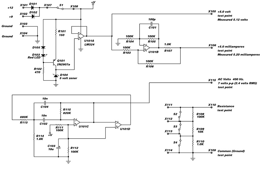
This inexpensive multimeter calibration tool can test the accuracy of any multimeter—from a $1,000 lab-grade HP to a $5–10 Harbor Freight wonder—or anything in between.
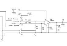
The true reference in this whole circuit is D104, a 5-volt Zener diode. Normally I’d just run a current-limiting resistor to the + supply (+V) and take the minor variation in current between a 9-volt battery and a 12-volt supply that will reflect a very minor variation in the Zener voltage. However, since this is a precision instrument, the current source comprised of D103-D105, Q101, and R101-R102 is not dependent on the supply voltage. It provides a constant 8 mA to the Zener over a very wide range of supply voltage. As another Weir two-fer, D103 is a red LED that provides an on-off indicator light.
U101A is connected as an extremely high input resistance unity gain amplifier. It takes nanoamperes (nanoampere —one billionth of an ampere) of current from the Zener reference voltage and outputs that same exact voltage, but with a relatively large current measured in tens of milliamperes.
U101B is connected in a little-known circuit called a “Howland Constant Current Source,” which is dependent only on the input voltage at the left end of R103. Since we spent a lot of time and circuitry making the voltage source so accurate, we might just as well use that voltage from U101A as the reference voltage for the current source. A milliameter connected to the output of U101B through R107 doesn’t care (within some reasonable limits) what the internal resistance of the meter is, but will drive about 5 milliamperes into the meter.
R108, R109, and R110 are connected in series, so that if switches S2, S3, and S4 are closed, the resistance between the resistance test point and the ground test point will be a dead short, or zero ohms. If S4 is opened, then there will be R110 (1.0K ohms) between the test point and ground. Likewise, if S3 is opened, then R109 (10K) or S4 is opened, and R108 (100K) will appear between the resistance test point and ground. If all three switches are open, then 111K (100 + 10 + 1) will appear between the test point and ground.
As I said, this inexpensive HF voltmeter doesn’t have much of an AC voltage range, but we had two leftover amplifiers, and a lot of you have oscilloscopes without a vertical channel amplifier, so U101C is configured as a 400 Hz filter and U101D is a comparator. When the slightest noise comes out of U101C, U101D makes it into a square wave, which is fed back to the filter, which outputs a clean sine wave, which drives U101D into more saturation, which is fed back to the filter, and around and around we go until U101D goes into complete saturation and the circuit stabilizes. This all takes place in a millisecond (one thousandth of one second) and the circuit winds up stabilizing at about 7 volts peak-to-peak (2.4 volts RMS) of fairly pure sine wave. This circuit will also drive headphones.
You are almost through; stay with me here. No matter how good a Zener diode you buy, or how precise an opamp you buy, you are stuck with passive components (resistors & capacitors) that have their own tolerances and errors. So, while I say you should be getting 5 volts for your DC test point, in practice it will never be 5.000000 volts. 4.98? 5.03? Probably, but the good news is that with modern components and techniques, it will stay that way for the foreseeable future. The trick is to borrow the best multimeter you can get and measure your own particular Test Box, then permanently mark the test point with your measured data. Now you have a truly accurate instrument for checking your inexpensive multitesters.
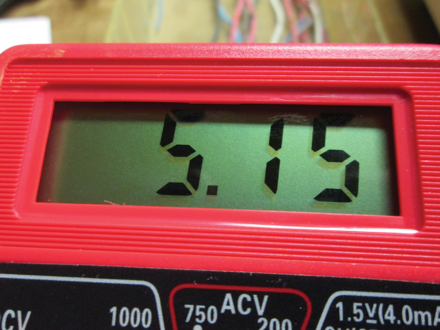
The multimeter test box came out with a test voltage of 5.12 volts, according to my $250 lab multimeter. The HF multimeter read 5.15 volts, a difference between the two of 0.6%.
For example, the KITPLANES® Multimeter Test Box—as constructed from randomly chosen parts from my engineering stock—came out with a test voltage of 5.12 volts, according to my $250 lab multimeter. The HF multimeter read 5.15 volts, a difference between the two of 0.6%. The lab meter read 5.20 milliamperes on the Test Box; the HF meter read 5.21. That’s a difference of 0.2%.

The lab multimeter read 5.20 milliamperes on the test box, while the HF multimeter read 5.21. That’s a difference of 0.2%.
Here are the values the lab meter read for resistance, and for comparison, I’ve put the HF meter values in parentheses: 100KΩ resistor reads 98.5K (98.6K), 10KΩ resistor reads 9.94K (9.92K), 1.0KΩ resistor reads 1.016K (1.000K). Now we have our KITPLANES® Test Box calibrated and ready to use.
I’ve still got the RV wind tee in the back of my mind, but one of our fellow pilots has a problem that I’m going to tackle first. It seems that several years of military airplane and explosion noise, plus a few dozen years of civilian airplanes and fire trucks, has made our friend quite hard of hearing—yet he uses the telephone quite easily. There is an answer, and I’ll share it with you in a future issue.
Until then…stay tuned…

![]()
Jim Weir is the chief avioniker at RST Engineering. He answers avionics questions in the Maintenance Bay forum at www.pilotsofamerica.com. His wife, Cyndi Weir, was his high school sweetheart 50 years ago and now she keeps Jim from making stupid blunders in spelling and grammar. Check out www.rst-engr.com/kitplanes for previous articles and supplements.


