Every now and again I have a good idea, but I can’t make it stretch to a full article. Here are a couple of good ideas that have bubbled to the top over the last couple of years, but couldn’t find a home in a single article.
How to Assemble a BNC Connector
I’ve been using BNC connectors for way more than half a century. As a matter of fact, I just disassembled a BNC connection I made in college (1965) that has been out in the weather for almost 50 years and the inside is as slick as a whistle. Not a hint of corrosion. It is all in how you do the original connector assembly.
I don’t care what your hangar neighbor’s brother’s hairdresser’s good buddy says about BNC connectors. The ones that last are not compression (solderless) connectors, but good old UG88 (male) and UG89 (female) solder-on connectors. These are solder-the-pin-on connectors and have a lifetime measured in dozens of years. The solderless connectors are what we call junk and I guarantee that within a year or two, they’ll give you fits.
Given that you will be using UG88/89 connectors, here is the drill for assembling them:
1. Be sure that you are using RG-58U with the solid center conductor. The stranded stuff is meant for cables that flex, and flex, and flex again—like a piece of test equipment. The solid center conductor is meant for piping RF signals around an airplane; it is much less lossy than the stranded stuff. In addition, the center pins of BNC connectors are not large enough for the stranded stuff.
2. The catch-dimension for BNC connectors is 3/8 inch (9.5mm). Remember this number.
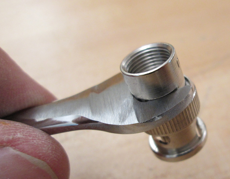
3. The real secret for BNC connectors is grinding down a cheap open-end 3/8-inch wrench to a thickness of 0.1 inch (2.5mm). This wrench will enable you to hold the body of the connector without using the ham-hand method of pliers.
4. The first thing to do is assemble the internal parts of the connector over the end of the coax. In order, put on the threaded nut, the flat washer, the rubber gasket, and the braid clamp with the pointed end of the clamp toward the gasket. When you assemble the connector, the braid clamp will do two things. First, it will press the shield braid of the coax firmly against the inside bottom of the connector. Second, it will expand the gasket to entirely seal the internals of the connector from the weather.
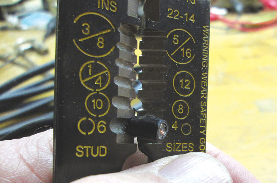
5. Now it is time to strip the coax. There are several tools available for this task, but I find a plain old manual stripper-crimper-screwcutter (Klein #1002) quite adequate for the job. Use the AWG #10 stripper hole and rotate the tool until the outer black plastic insulation can be removed from the coax. How much insulation to remove? Why, 3/8 inch, of course.
6. Bend the shield wires back until they are perpendicular to the coax. Make absolutely sure that there isn’t one little tiny shield wire anywhere on the clear plastic insulation around the center conductor. This is an absolutely critical step; one tiny shield wire can make the entire assembly worthless.
7. Now strip the clear plastic center conductor insulation back halfway to the braid. This will leave an equal amount of bare center conductor and clear plastic insulation out the end of the cable.
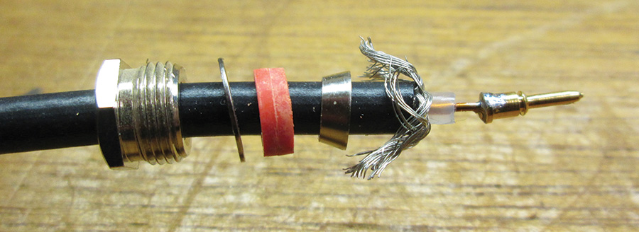
The parts (threaded nut, flat washer, rubber gasket, and braid clamp) of the BNC connector assembled onto the coax with the pin soldered on.
8. This is the point where a good vocabulary of words you didn’t learn in Sunday school will come in handy. Take a moderately hot (700 F) soldering iron (not a gun) and tin it well. Then wipe it very clean on a wet sponge. Put the gold center pin over the center conductor and place the hot iron on the shoulder between the small-diameter end of the pin and the larger-diameter rear section of the pin. Wait…and wait…and wait…until the junction of the pin and the center conductor gets hot enough to melt solder. Try your level best not to get any solder on the outside of the pin itself. If you do get solder on the rear section of the pin, you can use an X-Acto knife to scrape the solder off.
9. Some techs find it easier to put a small amount of solder on the center conductor, another small amount of solder on the hole in the back of the pin, and then heat the pin with the iron until the pin melts the two solders so that the pin slides onto the center conductor. Some are so brave as to use a small butane torch (like those sold to caramelize the sugar on crme brle) as a heat source. I haven’t had the intestinal fortitude (with a capital G) to use either of these techniques.
10. Whichever technique you use, insert the pin fully into the connector housing. It is an acceptable technique to pull the pin fully into the connector with long-nose pliers. The pin should be flush with the top of the housing. You will feel a very slight snap as the pin fully connects with the housing. Then it is a simple matter to stuff the shield wires, followed by the clamp, the gasket, the flat washer, and then thread the nut into the housing. Now the 3/8-inch ground-down wrench comes into play. Hold the flats on the body with the ground-down wrench and use another 3/8-inch wrench to tighten the nut onto the body. Done.
Build an Auxiliary Power Connector
At some time, we’ve all needed a temporary connection to the battery. Yet putting a “cigarette lighter” type connector on the panel just isn’t acceptable. Further, any connection to the battery like this needs some sort of protection device to keep full battery current from wreaking havoc in the aircraft.
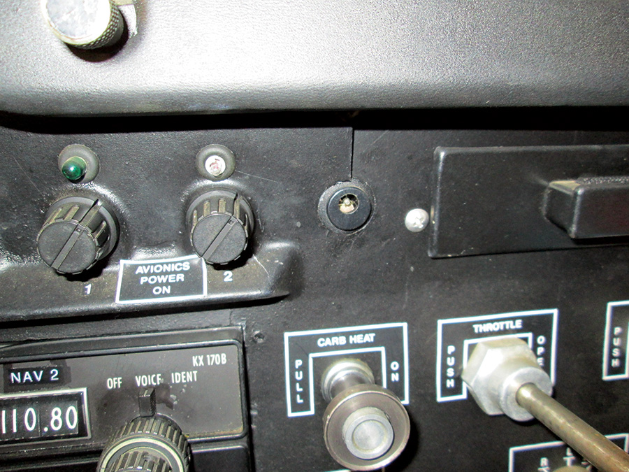
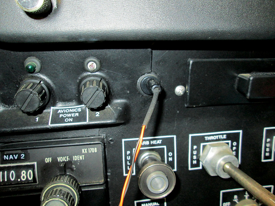
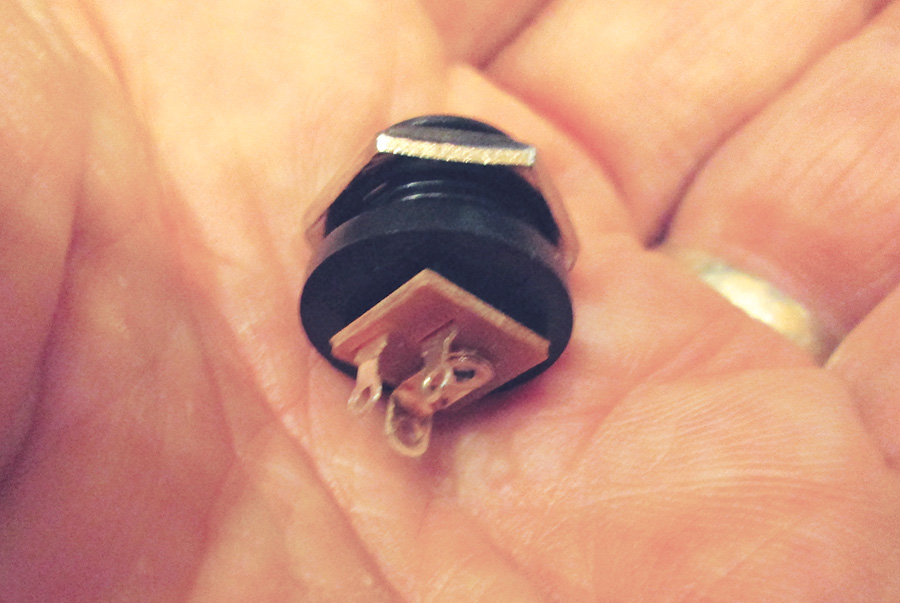
1. There is a power connector from Jameco and several other suppliers (Jameco #151590) that mounts in a -inch diameter hole. Amazingly enough, that is exactly the diameter of a 1950s era cigarette lighter hole. Now I would never in my life suggest that a production aircraft with a cig lighter be replaced with this connector, but I have this friend Ernie…
2. The production certification rules (which of course we don’t have to follow for Experimentals) allow us to take up to 5 amps directly from the battery before the master switch relay. The AC for this suggests that we place the fuse/breaker as close to the battery as possible and, in my world, it comes off the battery with #24 wire that will fuse itself with 10 amps or so. No combination of shorts will compromise the aircraft electrical system.
3. This is a metric connector that with the proper connector will allow two-way direct connection to the battery before the master switch relay. This allows for two things:
• We can draw up to five amps to power devices before the master switch comes on.
• We can pump up to five amps into the battery for charging before the master switch comes on.
Just a couple of really neat things I’ve been able to hang onto the KITPLANES Cessna test bed over the last couple of dozen years. I’ll pass on a few more from time to time. Until then, stay tuned…

![]()
Jim Weir is the chief avioniker at RST Engineering. He answers avionics questions in the Maintenance Bay forum at www.pilotsofamerica.com. His wife, Cyndi Weir, was his high school sweetheart 50 years ago and now she keeps Jim from making stupid blunders in spelling and grammar. Check out www.rst-engr.com/kitplanes for previous articles and supplements.

